
Voltage-level-indicator
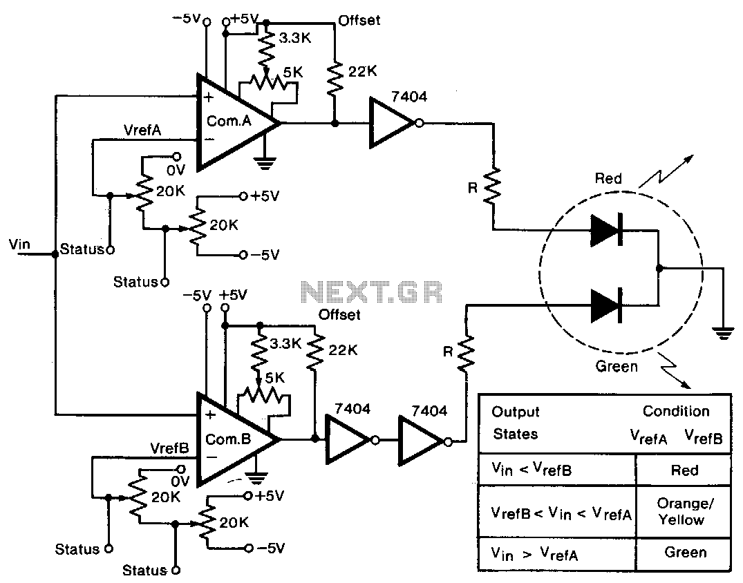
A tricolor LED serves as the visual indicator for voltage levels. The voltage to be measured is connected to two comparators in parallel. The first 20-KΩ trimmer sets a reference voltage between ±5 V, establishing the full-scale reference value. The second trimmer allows for fine adjustments, enabling selection of any reference voltage between 0 V and the full-scale voltage. This arrangement permits the selection of both positive and negative reference voltages. During initialization, a voltage equal to the reference voltage of each comparator is applied to the input terminal, and the offset balance potentiometer is adjusted to provide a reading between the high and low output voltage levels. An inverter following comparator A ensures that at least one diode is illuminated regardless of the input voltage. The two inverters following comparator B maintain the voltage largely unchanged while supplying sufficient current to light the diode. The resistance value must be chosen to ensure that the current through any single diode does not exceed the specified limit, typically 30 mA. The LED consists of a red and a green diode with a common cathode, and when both diodes are illuminated, they produce a third color, orange. If VcetA is greater than VcerB, the output states indicated in the diagram will apply.
The tricolor LED circuit operates as a voltage level indicator, utilizing a dual comparator setup to provide visual feedback based on the measured voltage. The two comparators are connected in parallel to allow for accurate voltage comparison against adjustable reference levels. The first trimmer, rated at 20 KΩ, is crucial for establishing a broad reference voltage range, accommodating both positive and negative voltages. The second trimmer is essential for fine-tuning the reference voltage, enabling precise adjustments to align with specific application requirements.
Initialization of the circuit involves applying a reference voltage to the input terminals of the comparators. The offset balance potentiometer is then adjusted, ensuring that the output reflects the correct voltage level, distinguishing between high and low states. This calibration step is vital for ensuring the accuracy of the voltage level indication.
The output configuration includes an inverter following comparator A, which guarantees that at least one of the diodes in the tricolor LED is illuminated, providing a clear visual indication of the voltage level. The inverters following comparator B serve to maintain the output voltage while supplying the necessary current to illuminate the LED. Careful selection of the resistance value is critical to prevent excessive current flow through the diodes, adhering to the maximum current rating of 30 mA, which ensures longevity and reliability of the LED components.
The LED itself consists of two diodes—red and green—sharing a common cathode. This design allows for the combination of the two colors to produce an orange hue when both diodes are activated. The operational logic of the circuit is such that specific output states are determined by the comparative voltage levels at VcetA and VcerB, providing a clear and intuitive visual representation of the voltage being measured. This circuit design is particularly useful in applications where visual feedback for voltage levels is necessary, such as in power supply monitoring or battery level indication systems.A tricolor LED, acts as the visual indicator of the voltage level. The voltage to be measured is connected to the two comparators in parallel. The first 20-KO trimmer defines a voltage between ±5 V and this becomes the full-scale value of the reference voltage. The second trimmer is a fine adjustment to give any reference voltage between 0 V and the full-scale voltage.
Thus, it is possible to select both positive and negative reference voltages. During the initialization procedure, a voltage, equal to the reference voltage of each comparator, is connected to the input terminal, and the offset balance potentiometer is adjusted to give a reading between the high and low output voltage levels. The inverter following comp A ensures that, whatever the input voltage, at least one diode is lit. The two inverters following comp B leave the voltage largely unchanged, but provide the current necessary to illuminate the diode.
The value of the resistance should be chosen so that the current through any single diode does not exceed the specified limit, usually 30 mA. The LED contains a red and a green diode with a common cathode. When both diodes are lit, a third color, orange, is emitted. With VcetA greater than VcerB, the output states given in the diagram apply. 🔗 External reference