
voltage level indicator
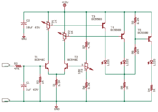
The circuit operates as a basic analog-to-digital converter, leveraging the characteristics of bipolar junction transistors (BJTs) to compare input voltage levels. The differential amplifier configuration formed by transistors T1 and T2 provides a means to amplify the difference between two input signals. This is essential for determining whether the input voltage exceeds predefined thresholds.
Transistors T3 and T4 act as comparators, responding to the amplified signals from T1 and T2. When the input voltage surpasses the threshold set by potentiometer P2, T3 conducts, allowing current to flow through LED1, signaling that the input is above the limit. Conversely, if the input voltage falls below the threshold defined by potentiometer P1, T2 activates, allowing T4 to illuminate LED2, indicating that the input is below the limit.
The behavior of T5 is crucial for indicating the state when both input conditions are unmet. In this scenario, T5 is biased due to the absence of voltage drop across resistor R5, allowing LED3 to light up, indicating a neutral condition where neither threshold is exceeded.
The circuit's design incorporates feedback mechanisms that enhance stability and responsiveness to input changes. The use of variable resistors (P1, P2, and P3) allows for fine-tuning of the thresholds, making the circuit adaptable to various applications. The beta parameter of the transistors, which indicates their current amplification capabilities, is a critical factor in ensuring reliable operation. Variations in beta due to manufacturing differences and environmental factors must be accounted for during circuit design and testing.
In summary, this circuit serves multiple applications, including FM tuning, stereo balance adjustment, and battery level monitoring, providing a versatile tool for educational and practical purposes in electronics.The circuit is here as it is of high educational value. I have not tested it. You can `simulate and test` or `wire it up and try` and let me know how it worked. The Circuit is also a simple analog to digital converter. You can use optos in place of LEDs. T1 and T2 make a differential amplifier. T3, T4 and T5 driving the LEDs are comparators. Now t o learn more on how they work you have to study circuits at 4QD-TEC and search Educypedia for more. Some pspice ideas here and at 101Science. com. When input voltage is increased T1 is turned on which leads to more base current for T3 which Lights LED1. When input voltage is less T2 turns on as it gets a better base current from P3 which turns on LED2 via T4.
When both LEDs are off T5 gets biased as no drop across R5 which lights the LED3 thru T5 hopefully. What you need to know is a small current Ib thru the base-emitter path in the direction of the emitter arrow will lead to a large Current Ic thru the emitter-collector path in direction of arrow. Ic = B * Ib where B - beta is the DC current gain, it could be 100-400 see Towers International Transistor Selector see chipdir.
Beta is different in each transistor you buy and varies with the test conditions and even with temperature and age. The LED1 and LED2 will indicate above or below Limits set by P2 and P1. The Limit Threshold itself is set at P3 i think. LED3 will light when Hi LED and Lo LED both are off. The applications of this circuit are FM tuning indicator, Stereo Balance Indicator (Wire T2 like T1 then we get two channel inputs) and battery level indicator.
🔗 External reference
Related Circuits
This circuit demonstrates that microprocessors, PCs, and modern ultra-accurate Digital-to-Analog Converters (DACs) are excessive for controlling four relays in sequence based on a control voltage ranging from 2.4 V to 12 V. By utilizing equal resistors in a ladder...

The term VCXO refers to a Voltage Controlled Crystal Oscillator. The frequency of this oscillator can be fine-tuned by varying the control voltage. VCXO clock generators are utilized in a range of applications, including digital telecommunications. VCXO circuits are essential...
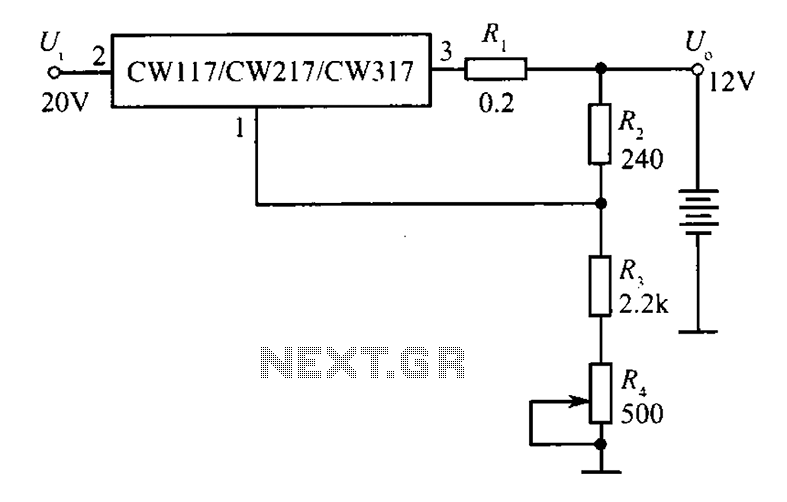
A 12V constant voltage charger is depicted. The power supply circuit shares the same basic design. The resistor R1, valued at 0.2 ohms, serves a limiting function, effectively increasing the internal resistance of the charger, which in turn reduces...
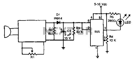
The acoustic detector consists of a Schmitt trigger IC555 connected to various components. When the input exceeds a certain voltage, the output will change state from high to low. R4 is used to set the threshold voltage. The acoustic detector...
Such supplies are often realised with dedicated integrated circuits nowadays but it's still interesting to give a look at old designs to understand the basics. The description outlines the evolution of power supply designs in electronics, emphasizing the transition from...
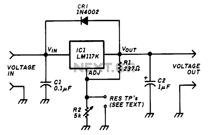
The variable voltage regulator allows for the adjustment of the output voltage of a fixed DC power supply between 1.2V and 37V DC, with the capability to supply output currents exceeding 1.5A. The circuit utilizes an LM117K three-terminal adjustable...