
Voltage-mode control and compensation: Intricacies for buck regulators
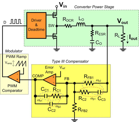
Voltage mode control is a widely used method in switching power supplies, particularly in buck converters. This technique regulates the output voltage by comparing it to a reference voltage and adjusting the duty cycle of the switching element accordingly. The control loop's stability and transient response are critical parameters that must be optimized to ensure reliable operation across varying load conditions.
Compensation in voltage mode control is necessary to achieve stable operation. It involves the design of a compensation network that shapes the frequency response of the control loop. Common compensation techniques include Type I, Type II, and Type III compensators, each offering different trade-offs in terms of phase margin, bandwidth, and transient response. The selection of the appropriate compensation scheme depends on the specific application requirements, load characteristics, and desired performance metrics.
When designing a buck converter, it is important to consider the following elements: input and output capacitors, inductor selection, diode characteristics, and PCB layout. Input capacitors must be chosen to handle the input voltage ripple, while output capacitors affect the output voltage ripple and transient response. Inductor selection impacts the efficiency and current ripple, and the diode must be rated for the expected current and voltage conditions.
Additionally, PCB layout plays a significant role in the performance of the buck converter. Proper grounding, trace widths, and component placement are crucial to minimize parasitic inductance and resistance, which can adversely affect the regulator's performance.
In summary, a comprehensive understanding of voltage mode control and compensation is vital for the effective design of buck regulator circuits. Proper selection of components and careful attention to layout will enhance the performance and reliability of the power supply design.Before designing with one of today`s powerful buck regulator ICs, you`ll want a thorough understanding of voltage mode control and compensation. .. 🔗 External reference
Related Circuits
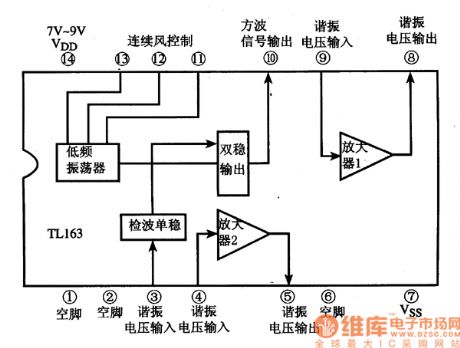
The following circuit illustrates the TL163 integrated circuit used in an ultrasonic remote control circuit diagram. Features include a detector, high-gain amplifier, and low-frequency capabilities. The TL163 integrated circuit serves as a pivotal component in ultrasonic remote control applications, facilitating...
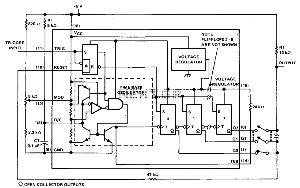
The µA2240 can be easily configured as a programmable voltage-controlled timer with a minimal number of external components. The modulation input (pin 12) allows for external adjustment of the input threshold level. A variable voltage is applied from the...
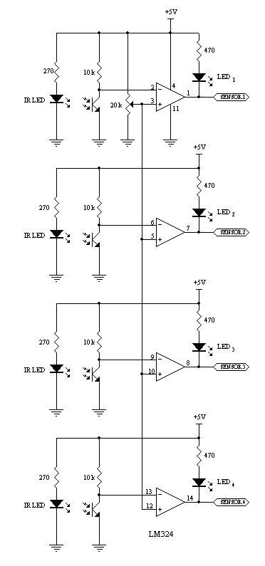
This robot utilizes two motors to control the rear wheels, while the single front wheel is free to move. It is equipped with four infrared sensors located on the underside to detect black tracking tape. When the sensors identify...
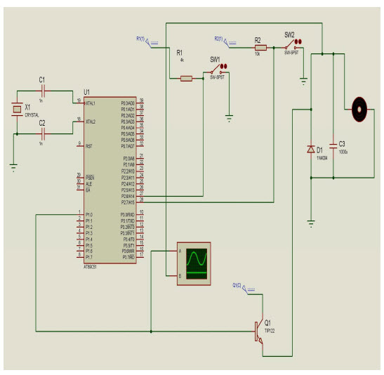
The objective of this project is to control the speed of a DC motor. The primary benefit of utilizing a DC motor is the ability to modify the Speed-Torque relationship to nearly any desired form. To facilitate speed control,...
The motor speed control for stitching machines utilizes a series of carbon buttons housed within an enclosure, which are activated by a foot pedal. As the pressure on the foot pedal increases, the motor speed is adjusted accordingly. The motor...
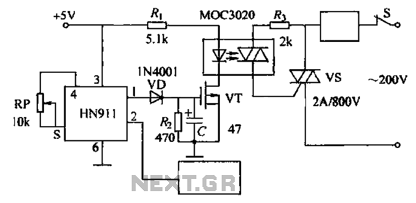
Automatic door control circuit diagram. It utilizes a pyroelectric infrared detection module, HN911, for human motion detection. A variable resistor (potentiometer) is used to adjust the delay time controlled by a transistor (VT). An optocoupler (MX: 3020) provides AC...