
Voltage Multiplier
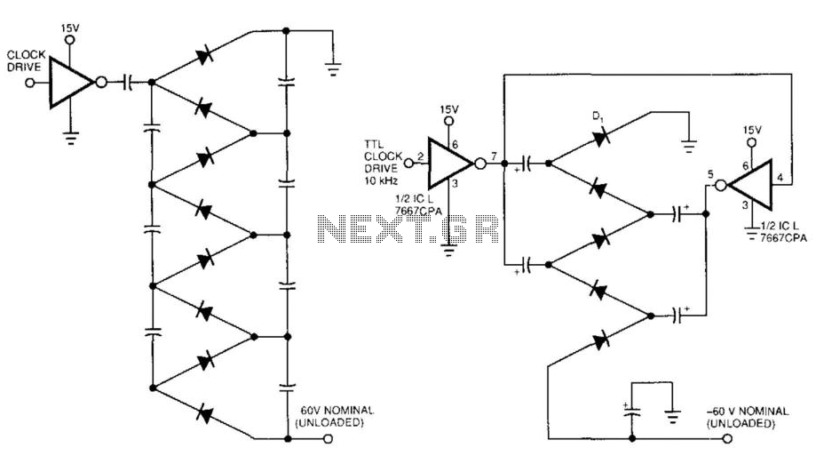
The circuit represented in Figure 99-1(a) demonstrates a high output impedance primarily due to the small effective capacitance of the series-connected capacitors. The design necessitates two diodes and two capacitors to achieve a DC output voltage that is a multiple of the rail voltage. However, this configuration suffers from significant voltage losses attributed to the forward voltage drops across the diodes.
In contrast, Figure 99-1(b) offers a more efficient approach by employing a parallel arrangement of capacitors, which allows for the utilization of smaller capacitors than those required in the series configuration of Figure 99-1(a). This parallel setup not only simplifies the component requirements but also reduces the output impedance when the same capacitor values are employed as in the previous design.
The operational dynamics of the clock source further differentiate the two circuits. In Figure 99-1(a), the clock source drives only one of the two capacitor strings, limiting the voltage multiplication effect. However, in Figure 99-1(b), the clock drives both capacitor strings in opposite phases, effectively doubling the voltage output per stage of the two diodes. This phase opposition is crucial as it enhances the overall efficiency of the voltage multiplication process.
To extract the DC output voltage, a final diode is included in the circuit, as both capacitor strings simultaneously carry the AC input voltage waveform. The inclusion of the ICL7667 dual-FET driver is significant as it accepts a TTL drive swing, providing a robust low-impedance push-pull drive to the diode string. This low impedance is particularly beneficial when leveraging a long string of diodes to elevate the output voltage beyond 100 V, starting from a low rail voltage, thereby making the circuit suitable for high-voltage applications. Figure 99-l(a)"s circuit exhibits a high-output impedance as a result of the small effective capacitance of the series-c onnected capacitors, and it exhibits considerable voltage loss due to all of the diode drops. Further, this circuit requires 2 diodes and 2 capacitors to produce a dc output voltage approximately times the rail voltage. Figure 99-1 (b)"s circuit multiplies more effectively using fewer diodes and capacitors. The parallel arrangement of the capacitors lets you use smaller capacitors than those required in Fig.
99-1(a). Alternatively, when using the same capacitor values of Fig. 99-1 (a), the output impedance will be lower. Whereas the clock source directly drives only one of the two strings of capacitors in Fig. 99-1(a), Fig. 99-l(b)"s clock drives both strings with opposite phases. This drive scheme doubles the voltage per stage of two diodes. A final diode is necessary to pick off the dc output voltage because both strings of capacitors now carry the - p ac input-voltage waveform. The ICL7667 dual-FET driver accepts a TTL drive swing and provides a low-impedance push-pull drive to the diode string.
This low impedance is particularly helpful when using a long string to raise output voltage to more than 100 V, starting from a low rail voltage. 🔗 External reference
Related Circuits
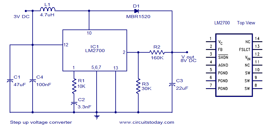
A simple DC to DC step-up voltage converter circuit schematic using the LM2700, which is a step-up switching converter. The LM2700 is a versatile step-up switching converter designed to efficiently convert a lower input voltage to a higher output voltage....
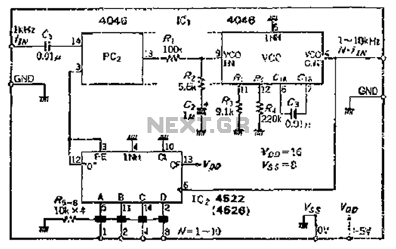
The CMOS IC 4046 Phase-Locked Loop (PLL) operates with a maximum frequency of 1 MHz. It is connected to a programmable divider, allowing it to process input frequencies. As the frequency increases by a factor of t, the circuit's...
The voltage reference circuit detailed below is a specialized implementation of the LM334 current source. It is characterized by a very low temperature coefficient for the output voltage and consumes only 10 µA at room temperature. This current may...
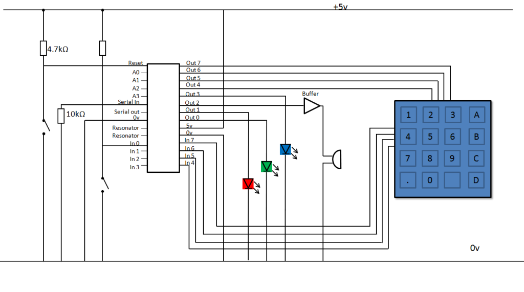
A keypad lock is being developed using a PIC microcontroller and a passive keypad with 8 pins, consisting of 4 input and 4 output pins. Each input pin corresponds to a row of numbers on a 4x4 keypad, while...
The LM317 is capable of providing extremely good load regulation, but a few precautions are needed to obtain maximum performance. For best performance, the programming resistor (R1) should be connected as close to the regulator as possible to minimize...
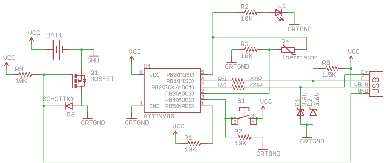
CRTGND is not equivalent to GND; CRTGND connects to the MOSFET drain or Schottky diode. A disadvantage of this circuit is the voltage drop when powered from the USB side due to the diode. The USB voltage can fluctuate...