
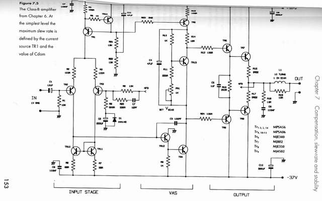
Voltage Multiplier for Power LED Driver
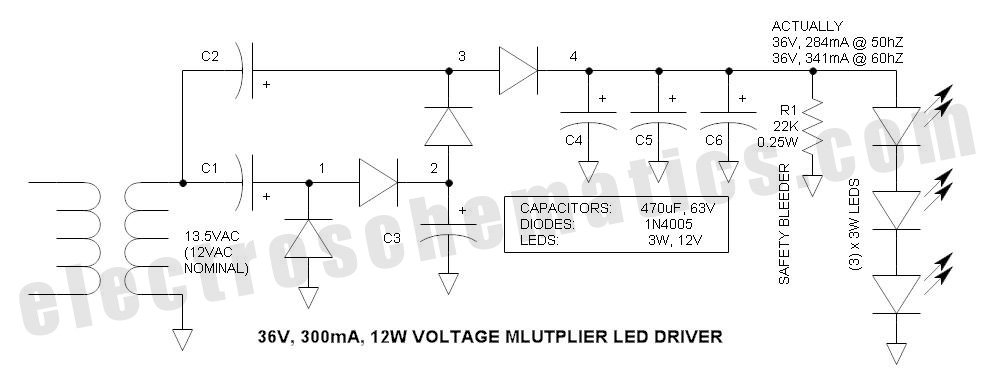
The power supply circuit leverages the inherent characteristics of the 12VAC landscape lighting transformer and the Stretch Voltage Multiplier to achieve efficient voltage regulation suitable for LED applications. The circuit architecture consists of a transformer, rectifier, and voltage multiplier stages. The transformer steps down the AC mains voltage to 12VAC, which is then rectified to DC. The voltage multiplier stage, configured as a quadrupler, utilizes capacitors and diodes arranged to boost the output voltage significantly while maintaining regulation.
In practical terms, the circuit can be designed using standard components easily sourced from electronics suppliers. The transformer should be selected based on the required load current and voltage ratings, ensuring that it can handle the power requirements of the connected LED devices. The rectification stage can be implemented using standard silicon diodes rated for the expected peak inverse voltage, ensuring reliability under load conditions.
The voltage multiplier stage requires careful selection of capacitors to ensure they can handle the voltage and ripple current. The capacitors should be rated well above the maximum expected voltage to prevent failure. The series connection of LEDs must be calculated to ensure that the total forward voltage drop aligns with the output of the multiplier, providing optimal brightness and efficiency.
This power supply circuit represents an innovative approach to driving LED applications, combining readily available components with a novel voltage multiplication technique, thus enhancing the functionality and safety of low-voltage lighting solutions.This power supply circuit is designed around the garden variety 12VAC landscape lighting transformer. Transformer availability and selection has long been a problem for the experimenter, and has often driven them to experiment with dangerous off-line capacitor limited power supplies.
However, the long neglected 12V landscape lighting transforme r is a good solution due to numerous advantages such as low cost, availability, and power variations (VA ratings). Directly rectifying the 12V transformer secondary is not a good choice because the rectified voltage is generally way high (typically 18VDC) due to peak detection of the sine wave ”in the past, this required a large, inefficient ballast resistor to drop the extra 6V.
However, a voltage multiplier (quadrupler) has some very interesting properties ” not only does it increase the voltage substantially, but it offers low voltage regulation that is ideal for powering constant voltage devices such as LEDs. The combination of the 12V lighting transformer and the voltage multiplier is like a match made in heaven.
The multiplier delivers 36V (loaded). To accommodate the higher output voltage, (3) 12V LED devices are connected in series to match this voltage. The voltage may be adjusted simply by varying capacitor size. Capacitors are garden variety aluminum electrolytics. The common 3 to 4W LED is bright, but a little low to be useful in general purpose lighting. Connecting (3) in series provides 9 to 12W, a much more useful level of illumination. The 12V LED unit is commonly available due to automotive and 12V battery applications. The initial circuit considered was the classic Cockcroft-Walton multiplier. While it functions, the output current tends to be too limited for this application. Note that all circuits tested here are quadruplers ” there are references to triplers on the web, but this is in error because multipliers multiply via cascading doublers so that there can be no odd factors.
To increase the current rating, I repositioned the input and output capacitors so that they are common to either the transformer secondary high side or ground. This variation seems simple enough, but I have been unable to locate prior art, so I am suggesting that this is new to the world.
I have coined the name: Stretch Voltage Multiplier. All capacitors are the same value. In the process of analyzing the graph, I plotted the effect of a fixed resistor ” this is the pink line. It blew my mind that the voltage multiplier source impedance behaves exactly as the fixed resistor ”I fully expected the plot to be non-linear.
The discontinuity below 20V is likely caused by reverse voltage on the polarized electrolytics ” under this condition, electrolytic capacitors tend to act as rectifiers ” operation in this region is not recommended. Unloaded, the voltage swings up to 74V ”fortunately, my capacitors did not smoke ” 63V capacitors are robust enough to tolerate a surge of this magnitude.
For this reason, the power must be switched at the transformer primary rather than the DC output. I think I have drawn the load line correctly. The lower the slope of the load line, the better the current regulation ” it indicates what happens to LED forward voltage over the temperature range, as well as the limits of manufacturing variations. The graph source is Bridgelux, an LED manufacturer: The input current indicates the presence of harmonics, but the waveform is not all that bad ” peak current is well under control.
I did not expect the high degree of symmetry. Power factor is obviously leading as expected. Capacitor ripple current is well within the current rating of garden variety capacitors. Check out this link for high current, small size, low cost Nichicon PW series capacitors ” note that the capacitor ripple current ratings are provided: Another curiosity is the impedance transformation. I should not be surprised because it is a law of 🔗 External reference
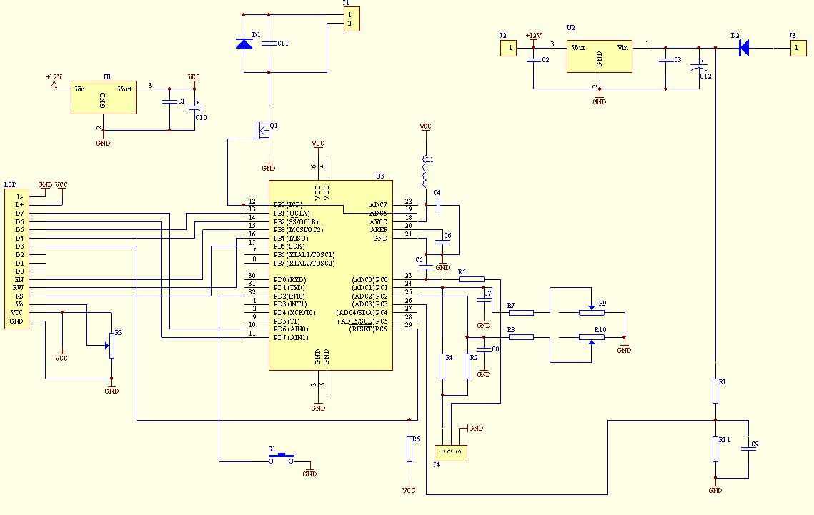
Related Circuits
This multimeter was designed to measure output voltage and current in a PSU, where the current sense shunt resistor is connected in series with load at the negative voltage rail. It needs only one supply voltage that can be...
I have had a lot of queries about getting a low power negative supply in cars, to power Linkwitz transform circuits and the like. There is a switchmode converter, but I must admit that it is overkill for what...
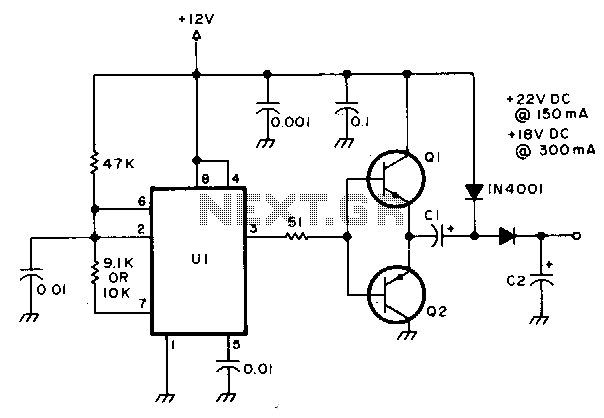
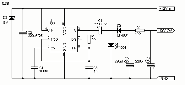
This circuit operates relays rated for 24V and 18V DC using a 12V power supply. It can be implemented with a wide range of PNP or NPN power transistors. Components include: U1: NE 555 timer; C1 and C2: 50...
This article is intended for individuals interested in constructing their own car amplifier. The fundamental calculations will be discussed below. Understanding these concepts will enable the construction of a car amplifier independently. The challenge in designing a car power...
The project is developed by Team Stark, with Gilbert as the leader and team members Martin and Janssen. The tasks have been divided into three parts. The first part includes camera control, login database, installer, and network setup, which...
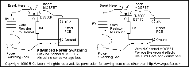
If you are an effects builder or repairer, you know that it is a good idea to protect the circuitry in the effect from the consequences of a reversed battery. While many older effects can withstand a momentary reversal,...
Warning: include(partials/cookie-banner.php): Failed to open stream: Permission denied in /var/www/html/nextgr/view-circuit.php on line 713
Warning: include(): Failed opening 'partials/cookie-banner.php' for inclusion (include_path='.:/usr/share/php') in /var/www/html/nextgr/view-circuit.php on line 713