
Voltage Reference LED indicator

Construction
The circuit was hand wired on a piece of phenolic board with one pad per hole. The parts were arranged so only one jumper, which was run across the component side of the board, was needed. The most difficult part of the construction was the mounting of the small 8 lead surface-mount LM4140. It turned out that I could place the package on the pre-etched pads on the phenolic board, but I had to split the pad that leads 6 and 7 attached to because they aren't to be connected together. Using a new X-Acto Knife blade and made two paralleled cuts across the copper doughnut, and removed a thin slice of copper to form a small gap between the pads. To soldering chip to the pads, I put a tin coating of neutral PH flux on the copper pads, tinned the pads with solder, removed the excess solder with a flux soaked piece of wire braid, then carefully and tediously nudged the package into position then tacked one corner lead down. After several iterations of tacking, inspecting, moving, etc., I managed to get the chip tacked down in the right position, then went around and heated the rest of the pins, adding solder where it looked like it was needed. The solder blobs on some pads appeared when I connected wires to the pads. Once the circuit had been built up and tested, I added four metal standoffs to hold the board off the workbench, and then cut a small piece of phenolic board to shape and hot-glued it to the back of the circuit board to protect the LM4140 and the wiring from being accidentally physically damaged. When applying the hot melt glue, I was careful to run it around the perimeter of the back of the board, keeping it off of the LM1440 and component leads as much as possible. I went around twice, building up a rim to hold the phenolic board off of the circuit board. As the glue had hardened, I placed the small piece of phenolic board on the rim and added more hot melt glue to hold the board in place.
Results
I measured the LM4104 on my two Fluke digital voltmeters, both about 10 years old and not calibrated since they left the factory. I was amazed to see that they both measured 1.024 volts. Another voltmeter, made by a manufacturer whose name one would recognize, measured the LM4140 as 1.031 volt. So, at this point, I would tend to believe the Flukes.
A detailed analysis of the circuit reveals several key components and their functions. The circuit begins with a keyed power input connector that ensures proper connection and prevents accidental reverse polarity. The inclusion of two 1N4007 diodes in series configuration acts as a series rectifier, while a shunt rectifier also using the 1N4007 component protects against reverse voltage, ensuring that the sensitive components downstream are safeguarded.
The 27-volt metal oxide varistor (MOV) serves a critical role in clamping voltage spikes to under 30 volts, thus providing an additional layer of protection for the 78L05 voltage regulator. The 78L05 is a low-dropout three-terminal voltage regulator that accepts an input range of +9.0 volts to +24 volts and outputs a stable 5.0 ± 0.25 volts. This regulated output is essential for powering the LM4140 precision voltage reference, which is sensitive to input voltage variations. The 78L05’s regulation significantly reduces the voltage sensitivity of the LM4140, improving its output stability.
A 3.3-volt zener diode is placed across the LM4140's output to prevent excessive voltage from reaching the reference chip, thus ensuring safe operation during accidental over-voltage conditions. The design allows compatibility with other voltage reference chips, provided they can tolerate the output from the 78L05 and the zener diode's clamping voltage.
The construction of this circuit on phenolic board with careful attention to the layout demonstrates a practical approach to prototyping. The hand-wiring technique utilized is particularly effective for low-volume applications or experimental setups, though it may not be suitable for mass production due to its labor-intensive nature. The use of hot glue to secure components and protect them from physical damage illustrates a thoughtful design consideration for durability in a laboratory environment.
In summary, the circuit presents a robust solution for providing a stable voltage reference while incorporating protective measures against voltage transients and reverse polarity, making it suitable for various applications in electronic design.A keyed power input connector, series rectifier and a shunt rectifier, both 1N4007, prevent reverse voltage from being applied to the power input. A 27 volt metal oxide varistor clamps the voltage to the 78L05 that follow it, to less than 30 volts, thus protecting the 78L05.
An input voltage of between +9.0 volts and about +24 Volts is needed to power the 78L05. The 78L05 in turn, provides 5.0 ± 0.25 volts for the LM4140 precision reference. This has two important benefits: The 78L05 keeps the input to the LM4140 from exceeding the maximum rated input voltage of 5.6 volts. It also keeps the input to the LM4140 constant, thereby removing up to 300 parts per million of output voltage per volt of input voltage of input voltage sensitivity. A 3.3 volt zener diode across the LM4140's 1.024 volt output limits the maximum voltage that can be applied to the LM4140's output by an accidental contact.
This circuit would work well with other voltage reference chips as long as the input voltage for the reference chip is compatible with the output of the three terminal regulator and of course if the reference voltage was significantly lower than the output protection zener diode's zener voltage. Varistors are uncommon parts in some labs. The varistor on the input can be omitted, or a zener diode of the appropriate rating could be substituted.
The LED and its associated 2.2 k resistor are only there to indicate that the circuit is on. It too can be eliminated without affecting the performance of the rest of the circuit. Construction The circuit was hand wired on a piece of phenolic board with one pad per hole. The parts were arranged so only one jumper, which was run across the component side of the board, was needed. The most difficult part of the construction was the mounting of the small 8 lead surface-mount LM4140.
It turned out that I could place the package on the pre-etched pads on the phenolic board, but I had to split the pad that leads 6 and 7 attached to because they aren't to be connected together. Using a new X-Acto Knife blade and made two paralled cuts across the copper doughnut, and removed a thin slice of copper to form a small gap between the pads.
To soldering chip to the pads, I put a tin coating of neutral PH flux on the copper pads, tinned the pads with solder, removed the excess solder with a flux soaked piece of wire braid, then carefully and tediously nudged the package into position then tacked one corner lead down. After several iterations of tacking, inspecting, moving, etc., I managed to get the chip tacked down in the right position, then went around and heated the rest of the pins, adding solder where it looked like it was needed.
The solder blobs on some pads appeared when I connected wires to the pads. Once the circuit had been built up and tested, I added four metal standoffs to hold the board off the workbench, and then cut a small piece of phenolic board to shape and hot-glued it to the back of the circuit board to protect the LM4140 and the wiring from being accidentally physically damaged. When applying the hot melt glue, I was careful to run it around the perimeter of the back of the board, keeping it off of the LM1440 and component leads as much as possible.
I went around twice, building up a rim to hold the phenolic board off of the circuit board. As the glue had hardened, I placed the small piece of phenolic board on the rim and added more hot melt glue to hold the board in place. Results I measured the LM4104 on my two Fluke digital voltmeters, both about 10 years old and not calibrated since they left the factory.
I was amazed to see that they both measured 1.024 volts. Another voltmeter, made by a manufacturer whose name one would recognize, measured the LM4140 as 1.031 volt. So, at this point, I would tend to believe the Flukes. I have an older voltage reference, which was based on Design Idea article in EDN Magazine back in the 1970's -its an LM723 voltage regulator chip connected so that the internal pass transistor acts as a heater, and the internal current limit transistor serves as a temperature sensor, so the chip could provide a stable temperature for the on-chip zener reference voltage.
Back on March 1, 1979, I calibrated this against a differential voltmeter with calibration traceable to the NBS (Now NIST). I had set the output of this LM723 based reference to 1.00019 volts. I connected this LM723 based reference to a bench supply and watched it on one of my Fluke DVM's. After a minutes of warm-up time, the reading settled at 1.000 volts. 🔗 External reference
Related Circuits
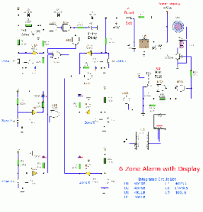
This circuit consists of a 6 Zone Alarm system with an LED display. The alarm system features 6 independent zones and includes a 7-segment LED display, along with one timed entry/exit zone. The 6 Zone Alarm system is designed to...
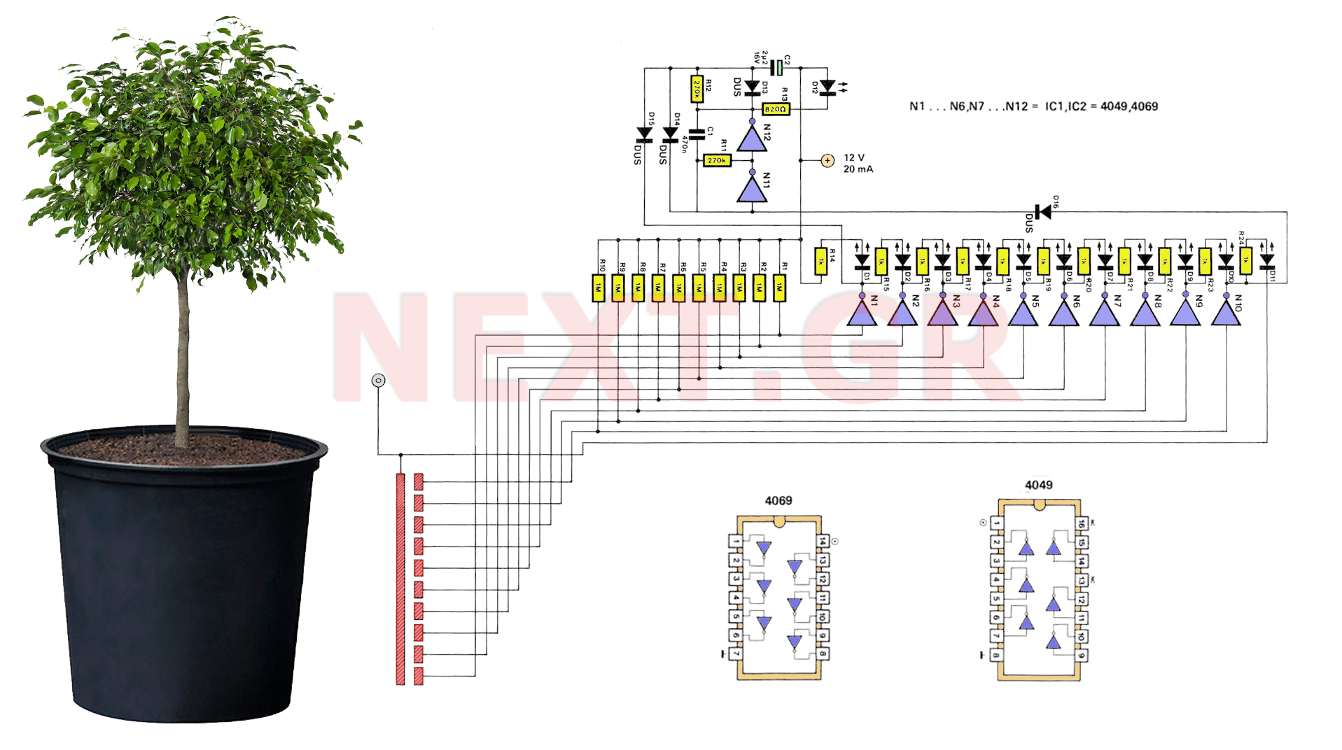
A series of LEDs is used to alert the gardener when plants require watering. By utilizing two conventional digital integrated LEDs along with a series of additional LEDs, this device serves as a practical tool for gardening. It detects...
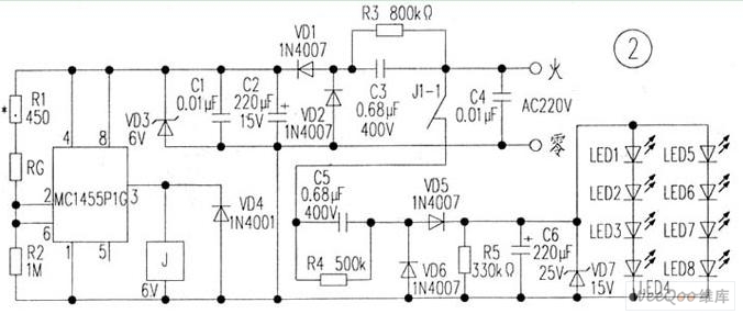
The circuit is depicted in Figure 1, while the electrical schematic diagram is presented in Figure 2. The AC voltage of 220V is reduced by components C3 and R3. The diodes VD1 and VD2 rectify the voltage, and capacitors...
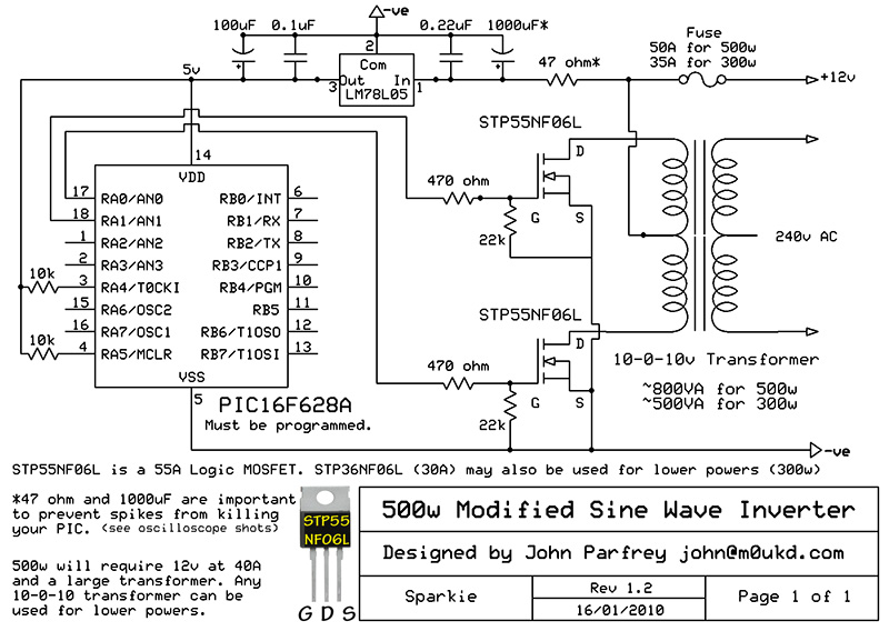
PIC controlled 500W Modified Sine Wave Inverter. The PIC16F628A is programmed to produce a logic 5V signal for 5ms at pin 17, followed by 15ms off. The described circuit implements a 500W modified sine wave inverter controlled by a PIC16F628A...

32.768 kHz; In MP3/MP4 devices, mobile phones, laptops, and other digital products, a real-time clock signal generating circuit is utilized, primarily composed of crystal resonators and TC5036/TC5048AP chip oscillators. This setup produces a raw 32.768 kHz crystal oscillator signal,...
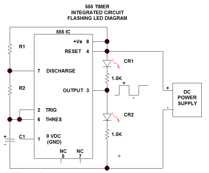
This section discusses one of the most useful Integrated Circuits (IC), commonly known as the 555 Timer chip. It is important to note that ICs... The 555 Timer IC is a versatile and widely used component in electronic circuits, primarily...