
Voltage·to-frequency-converter
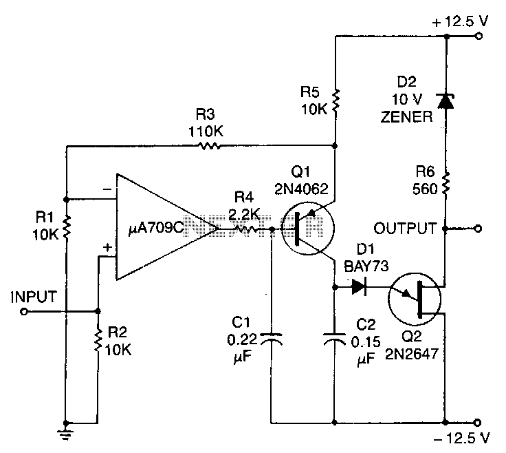
This circuit consists of a UJT oscillator where the timing charge capacitor C2 is linearly dependent on the input signal voltage. The charging current is determined by the voltage across resistor R5, which is precisely controlled by the amplifier.
The described circuit employs a Unijunction Transistor (UJT) oscillator configuration, which is known for its simplicity and effectiveness in generating timing pulses. In this setup, the UJT serves as the primary switching element, enabling the oscillation process. The capacitor C2 plays a critical role in timing, as its charging rate directly correlates with the input signal voltage. This linear dependency allows for precise control over the oscillation frequency, making the circuit suitable for applications requiring accurate timing signals.
The resistor R5 is integral to the circuit as it establishes the charging current for the capacitor. The voltage across R5 is regulated by an amplifier, which ensures that the charging current remains stable and predictable. This feedback mechanism is essential for maintaining consistent performance regardless of variations in the input signal.
To further enhance the circuit's functionality, careful selection of component values is crucial. The value of capacitor C2 will determine the time constant of the charging process, while the resistance of R5 will set the maximum current flowing into the capacitor. By manipulating these parameters, the frequency of oscillation can be finely tuned to meet specific requirements.
In practical applications, this UJT oscillator circuit can be utilized in timer circuits, pulse generators, and other electronic devices where precise timing is essential. The design's reliance on a linear relationship between input voltage and timing characteristics allows for straightforward calibration and adjustment, making it a versatile choice for various electronic projects.This circuit consists of a UJT oscillator in which the timing charge capacitor C2 is linearly dependent on the input sigoal voltage. The charging current is set by the voltage across resistor R5. which is accurately controlled by the amplifier. 🔗 External reference