
vu meter
The circuit utilizes 1K resistors to provide a threshold for LED activation, allowing them to illuminate in response to different audio signal levels. This feature is particularly useful in applications where visual indicators of audio signal strength are desired. The operational amplifiers can be configured in various ways, and the circuit's design allows for the integration of additional op-amps to enhance functionality or increase the number of channels monitored.
The inclusion of a 33K resistor at the input stage is crucial for ensuring that the signal remains at a manageable level, preventing distortion that could arise from excessively high input voltages. This resistor effectively acts as a voltage divider when combined with other components in the circuit, thus protecting sensitive elements from damage.
The circuit's capability to accept line-level inputs makes it suitable for integration with various audio devices, such as mixers, sound interfaces, or Hi-Fi systems. Moreover, with minor modifications, it can be adapted to handle speaker-level inputs, broadening its applicability in audio processing environments. This adaptability makes the circuit a versatile choice for audio signal monitoring and visual representation.The 1K resistors in the circuit are essential so that the LED`s turn on at different audio levels. This circuit is easily expandable with more op-amps, and is not limited to use with the LM324. The 33K resistor on the schematic is to keep the signal input to the circuit at a low level. The circuit in it`s current form will accept line level inputs from sources such as the aux out on a Hi-Fi, all though could be easily modified to accept speaker inputs. 🔗 External reference
Related Circuits
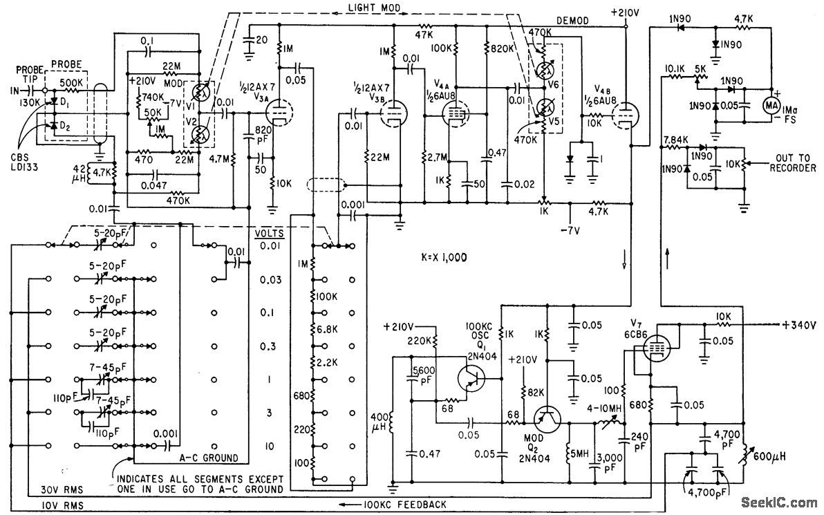
The circuit generates a low-frequency waveform with an amplitude that corresponds to an unknown RF voltage, utilizing a photochopper modulator (VI-V2) as an error detector. This arrangement provides seven voltage ranges from 10 mV RMS to 10 V RMS...
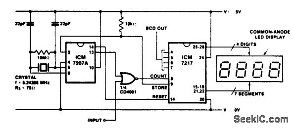
Precision frequency counter/tachometer. The ICM7207A provides a 1-second gating window along with the store and reset signals. The display reads hertz directly. When pin 11 of the ICM7207A is connected to V+, the gating time will be 0.1 seconds,...
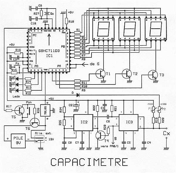
The proposed capacitance is a very powerful assembly to measure in 7 ranges capacitors of 1 pF to 999 uF, with an excellent precision of about 10^-3. The range change is fully automatic. The display shows 3 digits with...
The Car shows the distance a train travels on a 5 digit LCD display. The distance is indicated down to 1/100th of a mile (about the length of a 50 foot car) with an accuracy of approximately plus 2...
The circuit is connected in parallel with the output of the power amplifier and provides the signal level from the output. By adjusting resistance R1 in the input circuit, the power indication can be adapted according to the resistance...
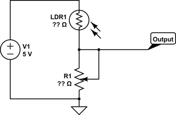
This part of the circuit is isolated from any other component, except for the 5V and ground connections. It includes LEDs and a shift register, which may not interact significantly. The LDR (Light Dependent Resistor) is utilized solely as...