
vu meter with led
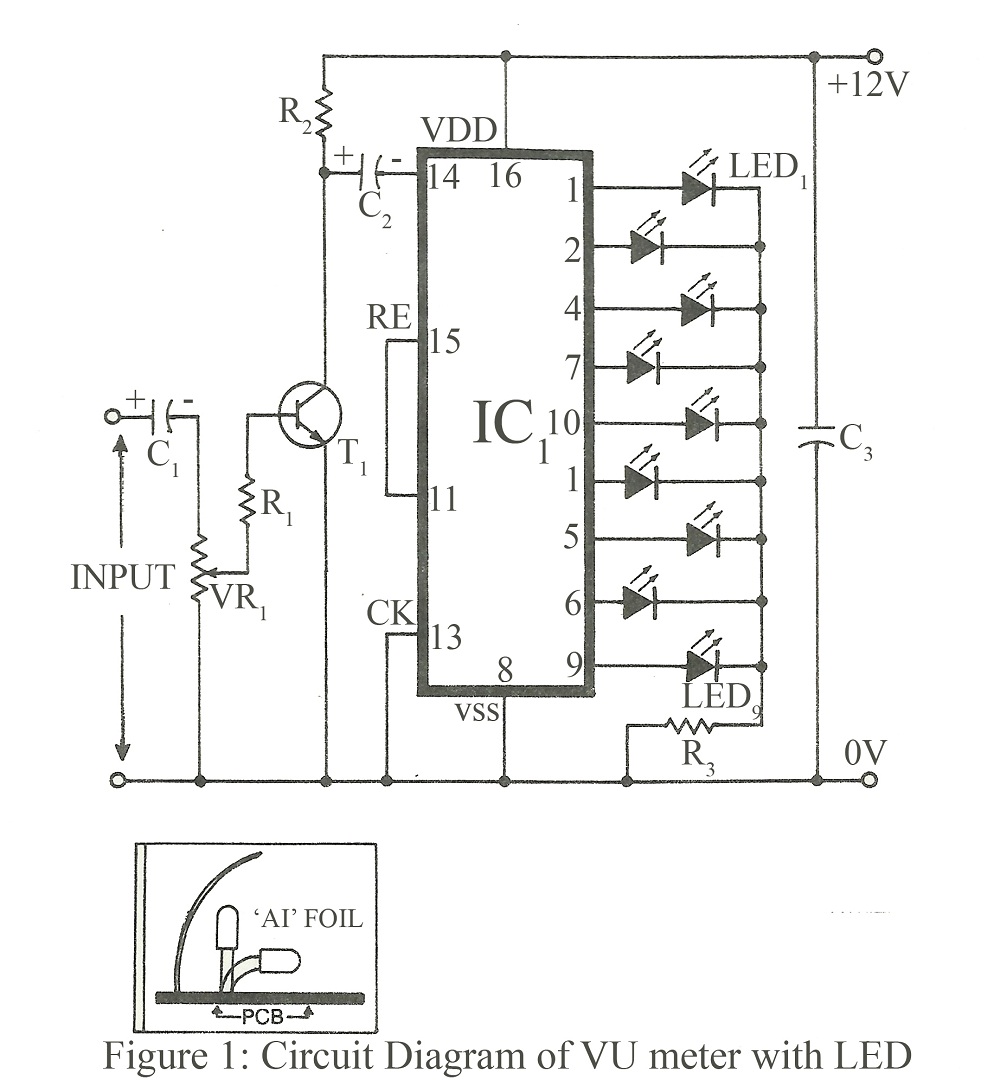
The circuit design utilizes the IC4017, a decade counter integrated circuit, which counts the input pulses received at its clock pin. This input is derived from a sound signal processed through a BC107 transistor, which acts as a switch to control the clock input based on audio levels. The IC4017 has ten output pins, each corresponding to a count from zero to nine. When the sound level increases, the transistor allows more frequent pulses to reach the clock input, thus incrementing the count and illuminating the corresponding LED.
For stereo applications, two IC4017 circuits are employed in tandem, ensuring that each channel of the amplifier is visually represented. The output from the main speakers is tapped for input, allowing the circuit to respond dynamically to the audio signals. Calibration of the circuit is achieved through the VR1 variable resistor, which can be adjusted to fine-tune the sensitivity of the LEDs to the audio input.
In configurations where fewer LEDs are desired, a connection from the output of one LED to the reset pin (pin 15) of the IC4017 can be utilized to manage the LED count effectively. It is crucial to ensure that pin 12 remains unconnected, as it does not serve a function in this application.
The visual representation of sound through the LED indicators enhances the overall experience of the audio system. By orienting a second LED towards the audience, the effect of the sound-to-light response is amplified, creating a more engaging atmosphere. This circuit not only adds a decorative element to the stereo amplifier but also provides a visual cue to the dynamics of the music being played.If you are making a stereo amplifier, or if you own one already, then do not hesitate to add this circuit. The entire circuit is wired around IC4017 whose clock input is tapped through transistor BC107. Basically, IC 4017 is a 1-of-10 decade counter or a decoder. To suggest the design, this circuit fills the gap between a simple 1-transistor sound -to-light and a unit using filter and main LEDs. But two units must be added for stereo operation. Circuit calibration is straight forward and should present no problem. The effect of sound reaching the input is to trigger IC to count one. This means that when the music gets louder, the LEDs move faster. If you wish to use fewer LEDs, a wire must link from the next LED and should go on to reset pin 15. Note that pin 12 doesnot have any connection. To tap the input to this circuit, it is advised to tap the output from the main speakers. VU Meter with LED If the LEDs do not move rapidly according to the music pitch, adjust VR1. If two LEDs are in parallel, the second one can be pointed towards the viewer for added effect. 🔗 External reference
Related Circuits
Microcontroller-Based Accelerometer Project. Just as a speedometer is a device that measures speed, an accelerometer is a device that measures acceleration. The microcontroller-based accelerometer project utilizes an accelerometer sensor to detect changes in velocity and orientation. This project typically involves...
This circuit is designed to provide a 4 LED bar graph that indicates the voltage of a common 3.6-volt Lithium-Ion rechargeable cell phone battery. The reference voltage is supplied by a TL431 programmable voltage source, which is configured to...
The meter was acquired from eBay and features a full-scale movement of 1 mA, already marked from 0 to 100. The original scale was removed, scanned, and modified to include "% NETWORK" markings using an image editor. The new...
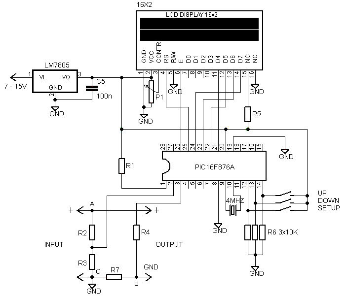
Voltmeters and ammeters with a PIC microcontroller can be utilized to measure voltage and current simultaneously. The configuration of voltmeters and ammeters using the PIC16F876A serves as a data processor for voltage and current measurements. This circuit employs a...
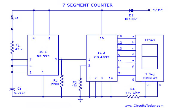
A simple seven-segment counter circuit with an LED display. This counter circuit diagram is designed using the IC CD 4033 as a counter, a 555 Timer IC, and a seven-segment LED display LT 543. The seven-segment counter circuit utilizes the...
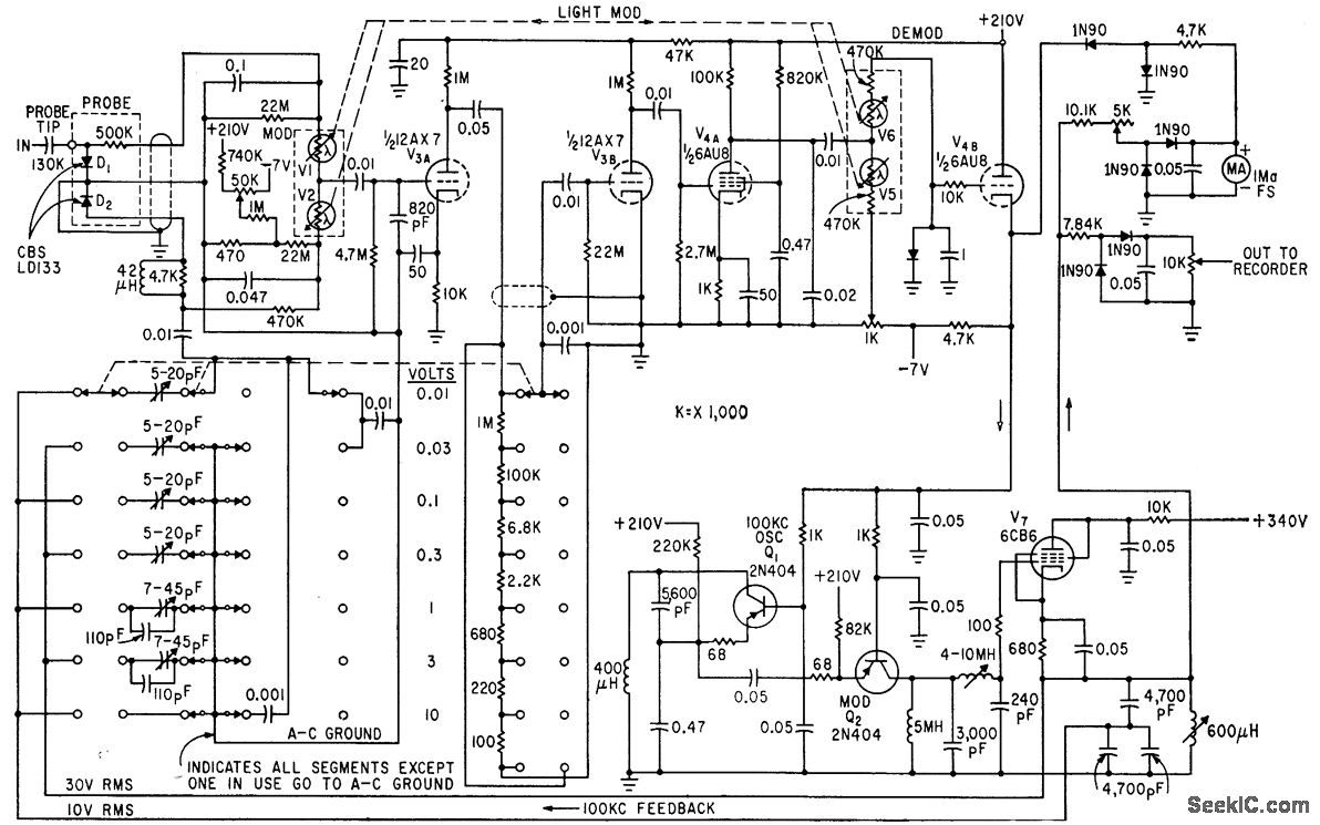
The circuit generates a low-frequency waveform with an amplitude that corresponds to an unknown RF voltage, utilizing a photochopper modulator (VI-V2) as an error detector. This arrangement provides seven voltage ranges from 10 mV RMS to 10 V RMS...
Warning: include(partials/cookie-banner.php): Failed to open stream: Permission denied in /var/www/html/nextgr/view-circuit.php on line 713
Warning: include(): Failed opening 'partials/cookie-banner.php' for inclusion (include_path='.:/usr/share/php') in /var/www/html/nextgr/view-circuit.php on line 713