
w201 thermometer question
The malfunctioning outdoor thermometer likely employs a thermistor or a similar temperature-sensing component to measure ambient temperature. In a typical design, the thermistor's resistance changes with temperature, allowing the device to convert this resistance change into a corresponding voltage signal.
The circuit may include a microcontroller or an analog-to-digital converter (ADC) to process the voltage signal from the thermistor. This processed signal is then used to drive a display, which could be an LCD or LED, showing the temperature in degrees Celsius.
Power for the thermometer is typically supplied by batteries or solar cells, depending on the design. An efficient power management circuit may be integrated to prolong battery life, often including components such as voltage regulators and capacitors to stabilize the power supply.
In cases where the display has blacked out, potential issues could include a faulty thermistor, broken connections, or a malfunctioning display driver. Troubleshooting would involve checking the integrity of the connections, testing the thermistor's resistance at various temperatures, and ensuring that the display circuitry is functioning correctly.
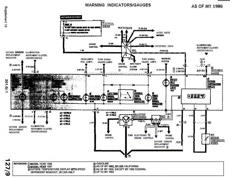
Overall, the replacement unit should be compatible with the existing mounting and wiring setup, ensuring a seamless installation and restoration of functionality to the outdoor thermometer.My `89 2.6 outside thermometer (Celsius) has blacked out and I was lucky by finding a good e-bayer who has one.. I bought it but appartently it was.. 🔗 External reference
Related Circuits
Related components PDF download: ICL7106CD4036. The LCD electronic thermometer circuit is illustrated. The temperature sensor KTY10 exhibits a strong linear relationship between temperature and resistance. Points A and B (Measurement display circuit) can be connected with a 100-meter wire....

Using a J-type thermocouple, this circuit can indicate temperatures from -350° to 400° with a 6-V supply or from -50° to +100° with a 3-V lithium battery. The AD954 produces a 10 mV/°C output to the MAX 138 digital...
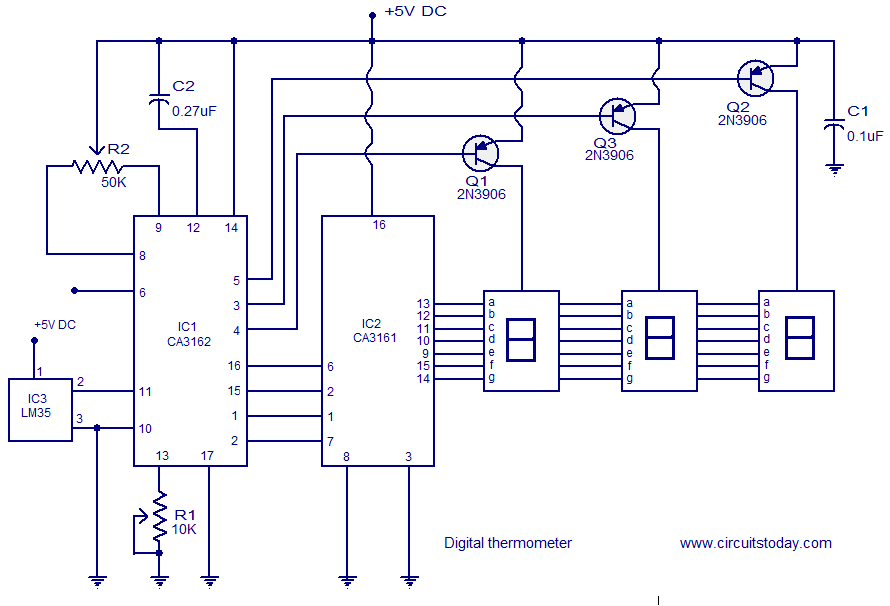
A simple digital thermometer circuit without a microcontroller and featuring a seven-segment LED readout is presented. The circuit utilizes three integrated circuits (ICs): CA3162, CA3161, and LM35. The CA3162 is a monolithic analog-to-digital (A/D) converter with a BCD output....
This digital thermometer indicates the temperature measured with an NTC using 7 LEDs. The circuit works using an opamp, the well-known 741, which amplifies the voltage difference between its plus and minus input. This amplification (sensitivity) can be set...

The thermistor RT, along with resistors R1, R2, R3, and variable resistor RP1, creates a temperature measurement bridge. At a temperature of 20°C, the configuration of R1, R3, and the adjustment of RP1 enables the bridge to maintain balance....

This circuit is intended for precision centigrade temperature measurement, with a transmitter section converting to frequency the sensor's output voltage, which is proportional to the measured temperature. The output frequency bursts are conveyed into the mains supply cables. The...
Warning: include(partials/cookie-banner.php): Failed to open stream: Permission denied in /var/www/html/nextgr/view-circuit.php on line 713
Warning: include(): Failed opening 'partials/cookie-banner.php' for inclusion (include_path='.:/usr/share/php') in /var/www/html/nextgr/view-circuit.php on line 713