
water detector circuit for your
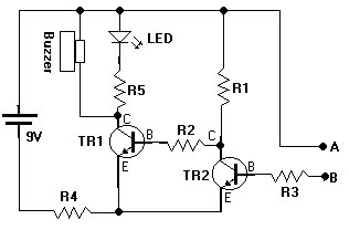
The water sensor circuit functions as a basic moisture detection system. It utilizes two transistors configured as a switch, which controls the buzzer and LED indicators. The circuit operates on a low voltage battery, ensuring it is energy-efficient and suitable for continuous use in a garden or indoor plant setting.
When the soil moisture level drops below a certain threshold, the resistance in the soil changes, triggering the transistors. This change activates the buzzer, producing an audible alert to indicate that the soil is dry. The LED serves as a visual indicator, providing a clear signal that attention is needed for the plant's watering.
The resistors are used to set the biasing conditions for the transistors and to limit the current flowing through the buzzer and LED, ensuring that they operate within safe limits. The choice of components allows for a compact and reliable design that can be easily assembled on a breadboard or a printed circuit board (PCB).
In summary, this water sensor circuit is an effective tool for plant care, combining simplicity in design with functionality to ensure plants receive adequate moisture. It is an excellent project for beginners in electronics, demonstrating fundamental principles of circuit design and component interaction.Today i want to share with you all my water sensor. This is my second successful project when i started with electronic hobby. This circuit is useful for your plant. How it`s work simple. It will beeping when your plant soil is dry and stop when it detect water. that all. It hard Don`t worry, it`s simple circuit construction. You just need 5 re sistors, 2 transistors, a LED, Buzzer and battery of course. Ok let`s construct the circuit. 🔗 External reference
Related Circuits
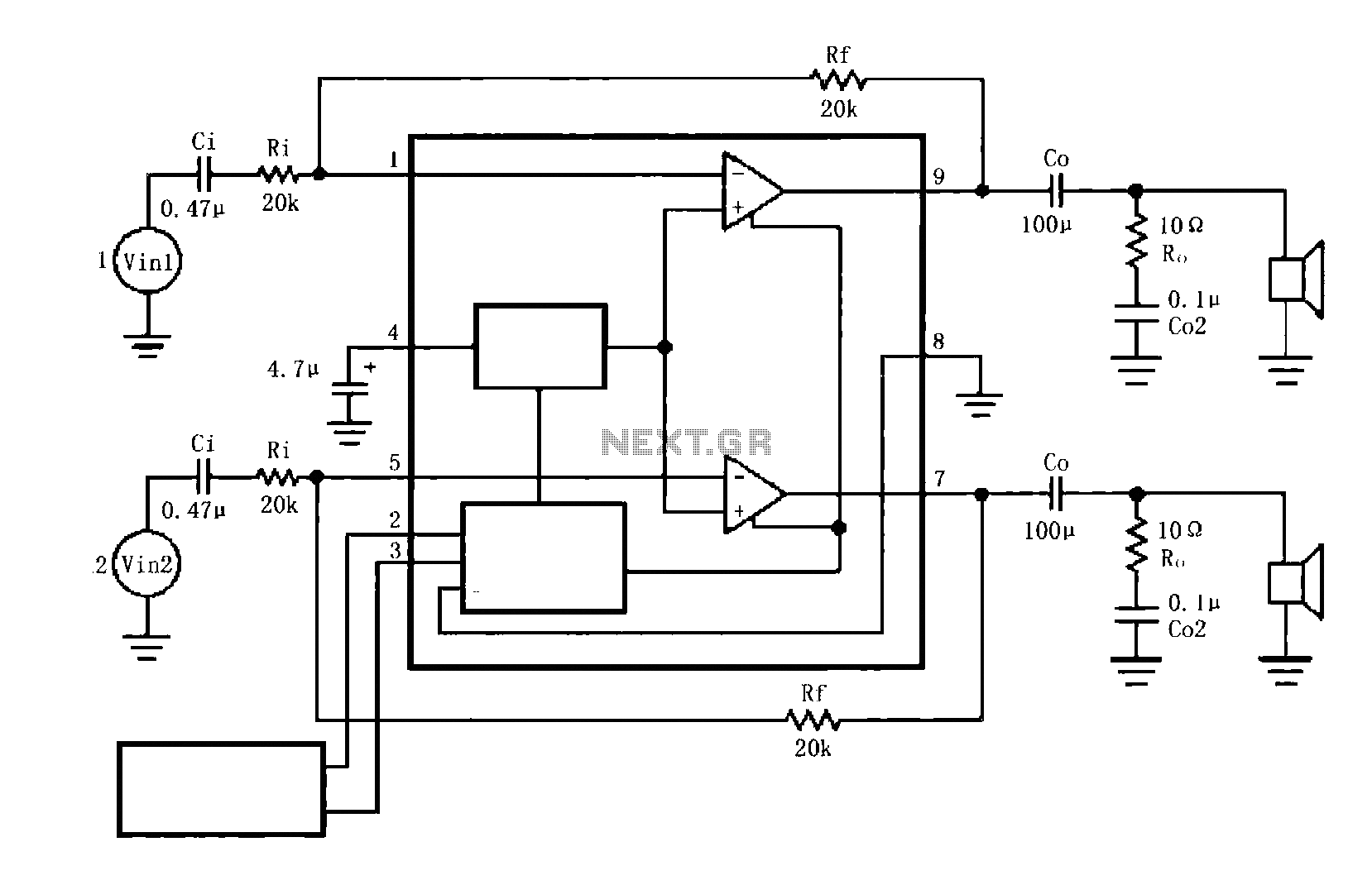
The circuit illustrated is a typical configuration for the LM4916 two-channel amplifier. The left and right channel audio signals are fed into the LM4916, which amplifies them internally. The output is then delivered through a coupling capacitor (Co) to...
The circuit diagram for a dynamic toy that produces eight sounds and five flashing lights is illustrated. It features the HFC3018 module, capable of generating eight distinct sounds, including step gunfire, aviation gunfire, game sight, telephone sight, bomb 1,...
This is a coincidence detector circuit. This circuit is very useful for monitoring complex logic circuits. This circuit has two inputs, A and B. If A and B are... The coincidence detector circuit is designed to identify when two input...
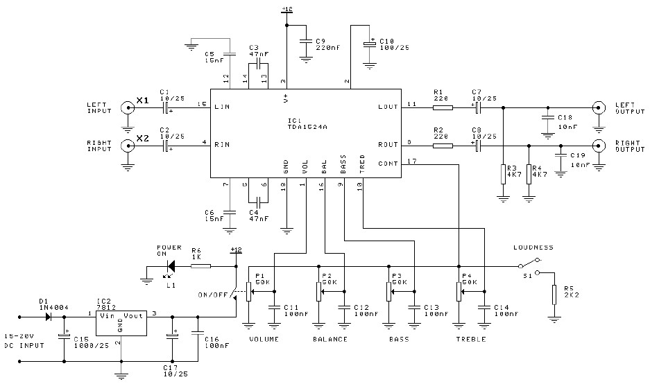
Preamplifier and tone control circuit based on the TDA1524A. The tone control circuit module is included in this preamplifier circuit, allowing for direct connection of the output channels to a stereo power audio amplifier circuit. This RIAA stereo preamplifier...

The circuit supplies 1 A at +5 V from the -48 V supply commonly used in telephone equipment. More: The National Semiconductor LM2575 is a simple switching regulator. The circuit utilizes the National Semiconductor LM2575, which is a step-down (buck)...
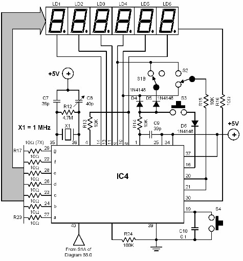
A digital audio frequency (AF) counter can be constructed using a minimal number of components by employing a single 7226B integrated circuit (IC) from Intensil, as depicted in the accompanying diagram. This circuit has an upper frequency limit of...
Warning: include(partials/cookie-banner.php): Failed to open stream: Permission denied in /var/www/html/nextgr/view-circuit.php on line 713
Warning: include(): Failed opening 'partials/cookie-banner.php' for inclusion (include_path='.:/usr/share/php') in /var/www/html/nextgr/view-circuit.php on line 713