
Water Level Indicator Circuit
The described circuit operates as a water level detection system utilizing a combination of integrated circuits and discrete components. The circuit's primary function is to monitor the water level relative to the steel rods, which serve as electrodes. The absence of water results in an open circuit condition between the metal can and the rods, leading to no current flow through the circuit based around IC1, which is likely a comparator or operational amplifier.
In this configuration, R5 acts as a pull-down resistor, ensuring that the voltage at the output remains at ground potential when the circuit is inactive. The window comparator formed by IC2A, IC2B, and transistor Q1 is crucial for determining the water level. The comparator checks the voltage levels at pins #2 and #5; when these pins are at zero volts, D3, presumably an LED, will illuminate, indicating the low water level condition.
Once the water level rises and makes contact with the first rod, the input pins #9 to #12 of IC1 are connected to the negative voltage, causing pin #13 to transition to a high state. This change in state can trigger further actions in the circuit, such as turning off D3 or activating additional components to manage the water level, depending on the overall system design.
The use of insulated wooden support for the rods is essential to prevent unintended grounding or short-circuiting, ensuring accurate readings from the water level. The design is likely intended for applications in water tanks, reservoirs, or similar environments where monitoring of water levels is critical for operational efficiency and safety. Overall, this circuit provides a reliable means of detecting water levels, with clear visual feedback through the illumination of D3.When the water-level is below the steel rods, no contact is occurring from the metal can and the rods, which are supported by a small insulated (wooden) board. The small circuit built around IC1 draws no current and therefore no voltage drop is generated across R5.
IC2A, IC2B and Q1 are wired as a window comparator and, as there is zero voltage at input pins #2 and #5, D3 will illuminate. When the water comes in contact with the first rod, pin #13 of IC1 will go high, as its input pins #9 to #12 were shorted to negative by means of the water contact..
🔗 External reference
Related Circuits
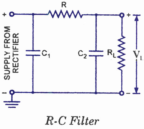
The disadvantages of pi-filters include higher costs, increased weight, larger size, and the external magnetic field generated by the series inductor. These issues can be mitigated by substituting the series inductor with a series resistor, referred to as an...
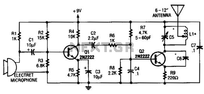
The intercom schematic provides a reliable communication line and is straightforward to construct. The circuit consists of an amplifier, two switches, and two loudspeakers. If additional stations (speakers) are desired, more switches can be incorporated into the circuit. The...
Every dedicated DIY enthusiast creates their own electronic dice using LEDs as indicators. This eliminates the need to physically roll dice; simply pressing a button activates the electronic mechanism. The design incorporates safeguards to prevent manipulation for improved outcomes,...
The vacuum tube remains relevant and functional in certain applications, such as in this continuous wave (CW) transmitter. The circuit is constructed in a traditional breadboard style on a wooden base. Old table radios serve as a valuable source...
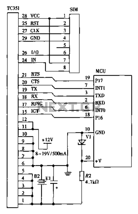
The design of a wireless data communication circuit is primarily intended for motor vehicles and fixed base station systems to facilitate close-range wireless data exchange. The circuit is based on the core chip nRF401 and its associated components. The...
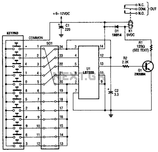
A block pinout diagram of the LS7220 keyless-lock IC is presented. The keypad must provide each key with a contact to a common connection. In this instance, the common connection is linked to the positive supply rail, allowing a...