
Water level indicator using 7-segment display circuit design
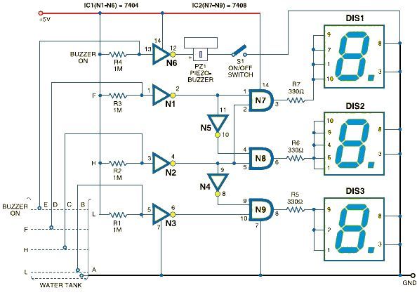
The water level indicator circuit operates by using the 7408 NAND gate IC to process signals from the five level sensors. Each sensor is strategically positioned at different heights within the tank to monitor the water level accurately. The sensor for common ground serves as a reference point, while the others are calibrated to detect specific water levels: low, half, high, and overflow.
When the water level falls below the low sensor, the circuit activates the corresponding output, illuminating the 7-segment display to show 'L'. As the water level rises and reaches the halfway mark, the half sensor triggers the display to change to 'H'. Finally, once the water level reaches its maximum capacity, the overflow sensor activates, and the display shows 'F' for full.
The 7404 hex inverting gate IC is used to ensure that the output signals are correctly inverted where necessary, allowing for a reliable indication of the water levels. This combination of components creates a simple yet effective water level monitoring system, suitable for various applications, including aquariums, water tanks, and reservoirs. The circuit design is efficient, cost-effective, and can be easily implemented with minimal components, making it an ideal project for both educational and practical purposes.Using this schematic electronic project can be designed a very simple water level indicator electronic circuit that uses a 7-segment display to indicate the water level (low, half and full)in the tank. This water level indicator electronic circuit shows the water level by displaying L, H and F for low, half and full, respectively.
This water level indicator electronic circuit is based on the 7408 quad two inputs and gates IC (that contains four input independent gates) and a 7404 hex inverting gates IC. The circuit uses five level sensors to sense the different water levels ( one for common GND, one for low, one for high one for half and one for overflow ).
🔗 External reference
Related Circuits
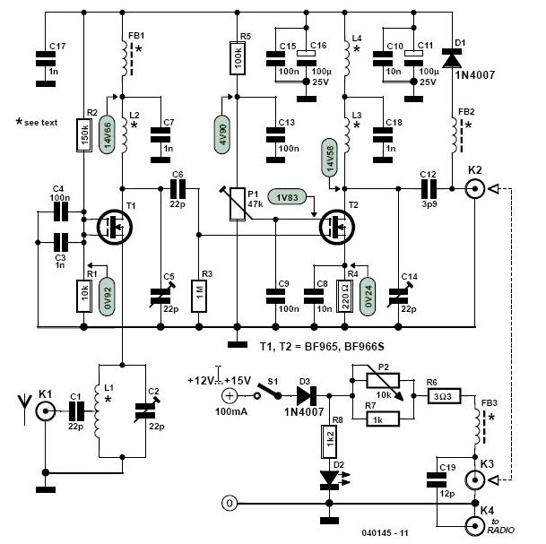
This high-performance two-stage antenna amplifier for the VHF FM broadcast band, when paired with a quality directional antenna, allows for the reception of distant (DX) stations. It significantly enhances the reception of FM signals that may otherwise be considered...

The digital circuit that is particularly useful is the One-Shot circuit, also known as a monostable multivibrator circuit. This circuit exhibits a specific behavior where it generates a single output pulse in response to an input trigger. The One-Shot circuit,...
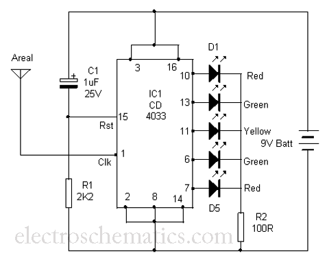
This is a simple tool designed to measure the level of radiation emitted by electrical or electronic devices. The circuit utilizes LEDs to create a running light pattern when it detects electromagnetic radiation from a source. It can detect...
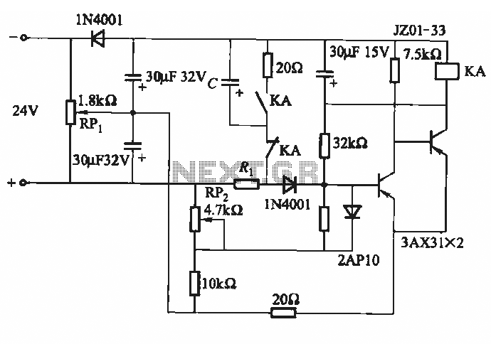
This circuit consists of five transistor time relay circuits designed for time relay exchange. It utilizes two different power supplies, maintaining the same circuit configuration. The delay time can be adjusted by modifying a potentiometer. The parameters for the...
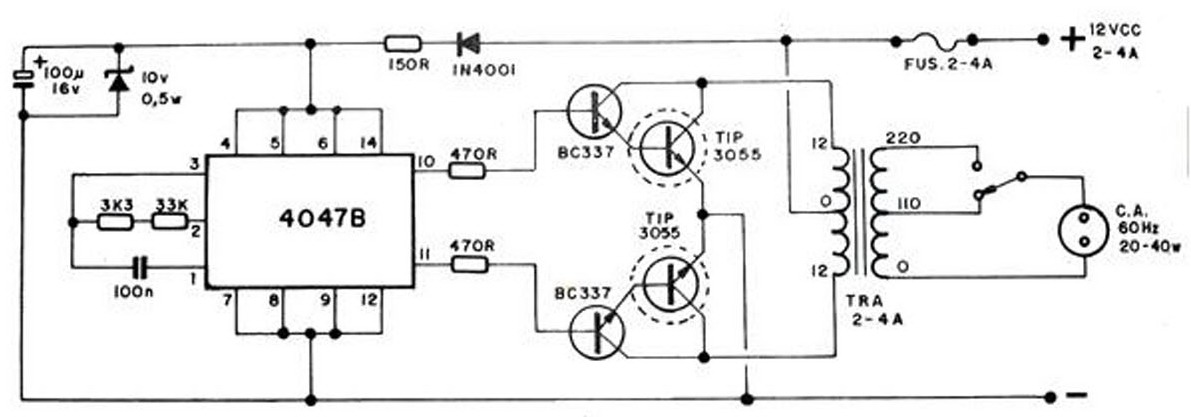
The converter transforms 12 VDC to 220 VAC, allowing for the conversion of 12 volts DC into 220 volts AC. The circuit diagram provided illustrates a simple converter circuit. This DC to AC converter can supply voltage for a...
The circuit is placed parallel with the exit of power amplifier and gives the level of signal from output. Changing resistance R1 in the input circuit, we adapt the indication of power in the resistance of loudspeaker that we...
Warning: include(partials/cookie-banner.php): Failed to open stream: Permission denied in /var/www/html/nextgr/view-circuit.php on line 713
Warning: include(): Failed opening 'partials/cookie-banner.php' for inclusion (include_path='.:/usr/share/php') in /var/www/html/nextgr/view-circuit.php on line 713