
Water-Level Sensor Uses Hysteresis

The water sensor circuit is designed to detect and monitor water levels within a specified range, providing feedback when the water level exceeds or falls below predetermined thresholds. The circuit typically consists of several key components: water level sensors, a microcontroller or comparator, power supply, and output indicators such as LEDs or alarms.
The water level sensors can be resistive or capacitive, depending on the application. Resistive sensors utilize two conductive probes placed at the desired upper and lower water levels. When water bridges the gap between the probes, it completes a circuit that can be read by the microcontroller or comparator. Capacitive sensors, on the other hand, measure the change in capacitance caused by the presence of water, offering a non-contact method of detection.
The microcontroller or comparator is programmed to compare the readings from the sensors against set thresholds. When the water level reaches the upper threshold, the circuit can activate an output device, such as a pump or an alarm, to indicate that the water level is too high. Conversely, if the water level drops below the lower threshold, the circuit can trigger another output to alert users or activate a refill mechanism.
Power supply considerations are crucial for ensuring reliable operation. The circuit can be powered by a DC source, such as batteries or a wall adapter, with appropriate voltage regulation to match the components' specifications.
Output indicators, such as LEDs, can provide visual feedback regarding the water levels. For instance, a green LED might indicate normal water levels, while a red LED could signal that the water level is too high or too low.
Overall, this water sensor circuit is a practical solution for applications in aquariums, water tanks, or industrial processes where monitoring water levels is essential for operational efficiency and safety.This design idea explains how to develop a water sensor circuit that can monitor upper and lower water levels 🔗 External reference
Related Circuits
By attaching a standoff to the center of a 2-inch, 8-ohm speaker, it can be transformed into a vibration sensor with a natural resonance below 100Hz, which is quite effective. The implementation involves hanging the speaker from the lid...
This light sensor switch circuit enables the automatic activation of a lamp when ambient light levels are low, such as during nighttime. The circuit keeps the lamp illuminated for a predetermined duration. When transistors T4 and T5 are activated,...
The schematic diagram has been modified to include a 220µF smoothing capacitor connected between the base of transistor Q1 and ground. This addition effectively mitigated the issue of relay chatter, which involved rapid on/off switching at light levels. The...

This small water sensor alarm circuit produces a loud warning sound when a humidity sensor detects the presence of water. The circuit utilizes the low-power comparator LM1801 from National Semiconductor. The reference voltage for the integrated circuit is established...
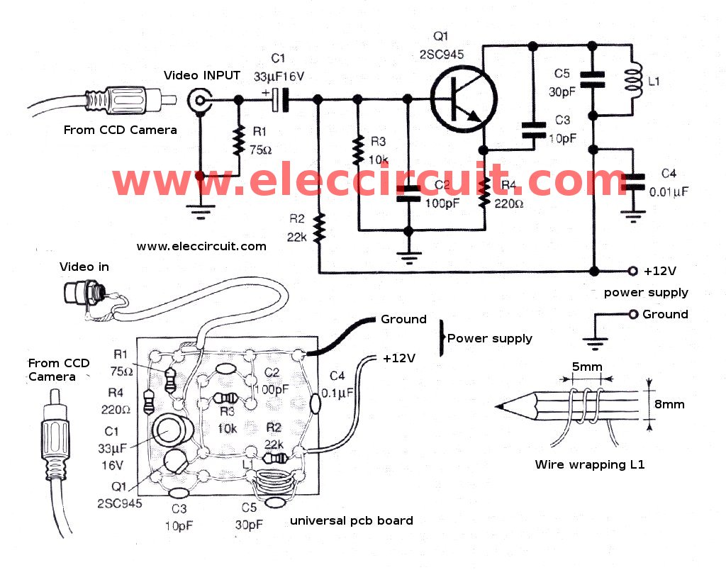
The CCD camera sensor is a very useful device that is compact in size while providing excellent quality. It can be easily installed with a television through the video input terminals, allowing for the transmission of modulated video signals...
The following circuit illustrates a PIR motion sensor circuit diagram. Features include simplicity and high efficiency, with operational amplifiers used to generate sound. The PIR (Passive Infrared) motion sensor circuit is designed to detect motion based on changes in infrared...