
whistle responder schematic circuit diagram
The circuit operates primarily through the integration of several key components. The electret microphone converts sound waves into an electrical signal, which is then amplified by IC1A. The amplification ensures that even faint sounds, such as a whistle, can be detected effectively. Following amplification, IC1B filters the signal to allow only the desired frequency range to pass, which is critical in environments with background noise. The use of a band-pass filter ensures that the device remains sensitive to the specific frequency of the whistle while ignoring other sounds that may trigger false positives.
The output from the band-pass filter is fed into IC1C, which acts as a Schmitt trigger. This component is crucial for converting the analog audio signal into a clean digital signal, effectively eliminating noise and ensuring that the subsequent stages of the circuit receive a stable input. The square wave output from the Schmitt trigger is then processed by IC1D, which is configured as a monostable timer. This timer introduces a two-second delay, which allows the circuit to remain inactive for a brief period after detecting a whistle, thereby preventing rapid successive triggering.
The output from IC1D is connected to the astable multivibrator formed by IC1E and IC1F. This configuration generates a square wave oscillation at a frequency between 3 to 5 Hz, which is suitable for driving the transistor Q1. The transistor acts as a switch, controlling the power to the buzzer BZ1. When activated, BZ1 produces the intermittent beeping sound, alerting users to the presence of a whistle within the detection range.
Overall, this circuit design is effective for applications requiring sound detection and alerting, such as security systems or personal safety devices. Its ability to filter out unwanted noise while selectively responding to specific sound frequencies enhances its reliability and functionality in real-world scenarios.This device beeps intermittently for about two seconds when a person in a range of around 10 meters emits a whistle. The first two inverters contained in IC1 are used as audio amplifiers. IC1A amplifies consistently the signal picked-up by the small electret-microphone and IC1B acts as a band-pass filter, its frequency being centered at about 1.8KHz.
The filter is required in order to select a specific frequency, the whistle`s one, stopping other frequencies that would cause undesired beeper operation. IC1C is wired as a Schmitt trigger, squaring the incoming audio signal. IC1D is a 2 second-delay monostable driving the astable formed by IC1E & IC1F. This oscillator generates a 3 to 5Hz square wave feeding Q1 and BZ1, thus providing intermittent beeper operation..
🔗 External reference
Related Circuits
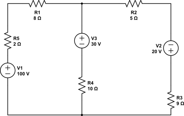
Using the superposition theorem, it is necessary to determine the current at all three nodes of the circuit. The current from the source, denoted as i_1, represents the current through V1 when other voltage sources are shorted out, in...
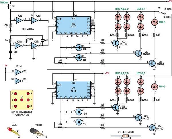
This circuit utilizes two 4516 integrated circuits (ICs) to simulate a game involving two dice. A switch is included to select whether one or two dice will be activated with each press. A 9-volt battery is sufficient for power...
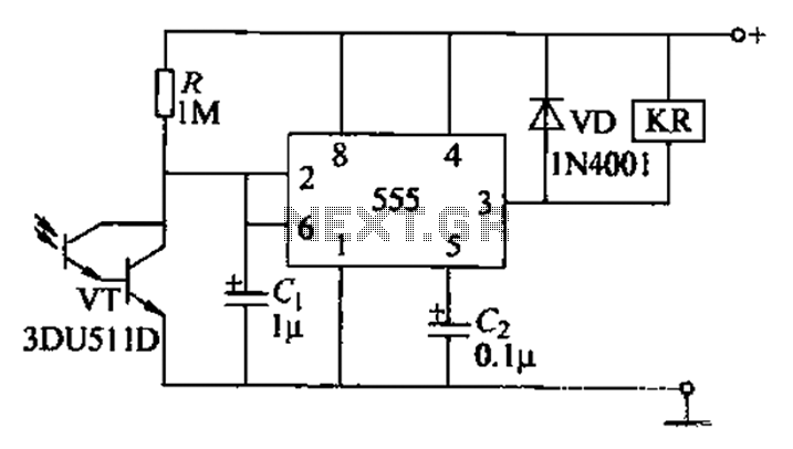
The circuit utilizes a Darlington-type phototransistor as the sensing element, which enhances sensitivity to low light levels, making it suitable for detecting reflected light signals. When the Darlington phototransistor is exposed to light, its resistance decreases, causing the voltage...
The first BC109C transistor (on the left side) functions as a buffer, offering the circuit a high input impedance of approximately 250k ohms and a voltage gain slightly less than unity. As the Baxandall tone control circuit is a...
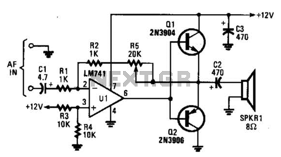
The circuit is designed around an LM741 operational amplifier configured as an inverting amplifier. It is utilized to drive complementary transistors (Q1 and Q2). The feedback loop of the op-amp incorporates the base-emitter junctions of both transistors, which aids...
This circuit is designed to prevent further damage to old equipment that may be in unknown condition, particularly to devices that are already shorted. The circuit functions as a protective measure for vintage or malfunctioning electronic devices. It is particularly...