Who-is-first

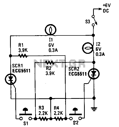
This control circuit utilizes two silicon-controlled rectifiers (SCRs) to ensure that only one lamp is illuminated at any given time. The first lamp (I1) is activated by SCR1, which is triggered when switch S1 is pressed. Similarly, the second lamp (I2) is controlled by SCR2 and switch S2. When both switches are in the open position, neither lamp is lit due to insufficient gate current to trigger SCR2 into conduction, preventing lamp I2 from lighting. If switch S2 is pressed before S1, the opposite scenario occurs. To turn off the light once one of the SCRs is activated, switch S3 must be opened.
The circuit operates on the principle of latch behavior provided by the SCRs, which are four-layer semiconductor devices that act as switches. When one SCR is triggered into conduction, it continues to conduct until the current flowing through it drops below a certain threshold, known as the holding current. This design ensures that only one lamp can be lit at a time, thus providing a clear indication of which switch has been activated.
The control circuit can be implemented using a straightforward schematic. The two SCRs (SCR1 and SCR2) are connected in parallel, each with its respective lamp (I1 and I2) and switch (S1 and S2). The gate terminals of SCR1 and SCR2 are connected to the switches, allowing them to be triggered when the switches are closed. A resistor may be included in series with the gate terminals to limit the gate current, ensuring safe operation and preventing damage to the SCRs.
In addition to the primary switches, a third switch (S3) is included in the circuit to facilitate the turning off of the lamps. When either SCR is triggered and the corresponding lamp is lit, the operator must open switch S3 to interrupt the current flow, allowing the SCR to turn off. This feature enhances the usability of the circuit, providing a manual control option for the operator.
Overall, this SCR-based control circuit is an effective solution for applications requiring single lamp indication with clear operator control, ensuring that only one lamp is illuminated at any time while providing a straightforward means of turning off the lights.Using two SCRs, this control circuit is designed to lock out the other SCR when one has been triggered, so only one lamp will light. Indicator lamp Il is controlled by SCRl. The operator simply presses switch Sl. Lamp I2 is similarly controlled by S2 and SCR2. With both switches open, neither lamp is lit. The result is insufficient gate current to trigger SCR2 into conduction, so lamp I2 does not light.
If S2 is pressed first, the reverse situation occurs. Once one of the SCRs is activated, it is necessary to open S3 to tum the light off.