
Wide-bandwidth-peak-detector
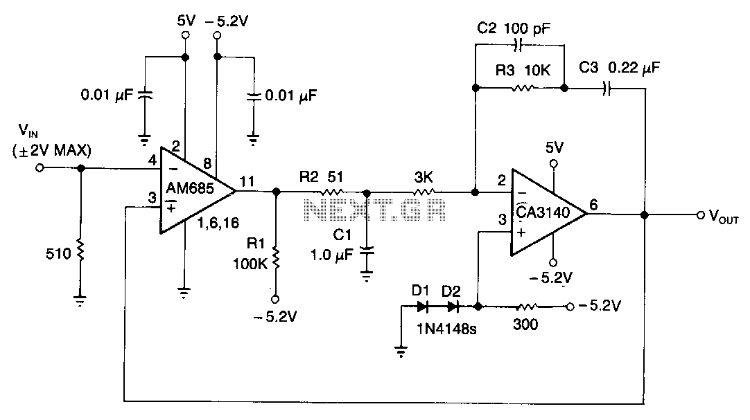
This circuit is capable of detecting positive peaks for signal frequencies exceeding 5 MHz, achieving an accuracy of ±1% for signal amplitudes ranging from 400 mV to 4 V peak-to-peak across sine, square, and triangular waveforms. The AM685 comparator output increases when the voltage at the non-inverting input (VrN) is more negative than the output voltage (Vout). This high output from the comparator subsequently charges capacitor C1 in a positive direction. The CA3140 operational amplifier amplifies the voltage across C1 relative to the ECL switching threshold voltage of -1.3 V, which is established by diodes D1 and D2. For repetitive waveforms, each cycle incrementally raises the output voltage (Vaur) until it matches the peak input value. The peak detection is facilitated by the comparator's open-emitter output, allowing C1 to charge quickly through resistor R2 while discharging slowly through both R2 and resistor R1.
Reducing the capacitance value of C1 results in shorter system response times. Although the circuit is unable to detect negative peaks, it can be adjusted to measure the peak-to-peak value of bipolar signals that are symmetric around ground. This adjustment can be achieved by dividing Vout by 2 using two 1 kΩ resistors and supplying the comparator with Vout/2 instead of Vout.
This circuit is designed for high-frequency applications where precise peak detection is essential. The AM685 comparator serves as a critical component, ensuring that only the positive peaks of the input signal are processed. The operational amplifier CA3140 is employed to provide necessary gain, which allows for the accurate representation of the voltage across C1 in relation to the established voltage threshold. The use of diodes D1 and D2 to set the ECL switching threshold is a common practice in high-speed circuits, ensuring that the comparator functions effectively within its operational limits.
The capacitor C1 plays a pivotal role in the timing characteristics of the circuit. Its charging and discharging rates are determined by the resistors R1 and R2, which influence the response time of the peak detection. By optimizing these component values, the circuit can be tailored for specific applications, ensuring rapid response to signal changes while maintaining accuracy.
For applications requiring the detection of bipolar signals, the proposed modification to divide the output voltage allows the circuit to accommodate a wider range of input signals, expanding its versatility. This capability is particularly useful in environments where signals may fluctuate around ground potential, necessitating a reliable method for measuring peak-to-peak values without losing critical information. Overall, this circuit design exemplifies a robust solution for high-frequency peak detection, suitable for various electronic applications.This circuit can detect the positive peaks for signal frequencies higher than 5 MHz. It yields ±1% accuracy for 400 mV to 4 V pk-pk signal amplitudes on sine, square, and triangular waveforms. The Am685 comparator output increases whenever VrN is a greater negative voltage than Vour; the high comparator output, in turn, charges C1 in a positive direction.
The CA3140 op amp amplifies the C1 voltage with respect to the ECL-switching-threshold voltage ( -1.3 V) developed by diodes D1 and D2. For repetitive waveforms, each cycle boosts Vaur until it equals the peak input value. The peak-detection process is aided by the comparator"s open-emitter output, which allows C1 to charge rapidly through R2, but to discharge slowly through R2 and Rl.
Reducing the value of Cl shortens system-response times. Although the circuit can"t detect negative-going peaks, it can be modified to measure the pk-pk value of bipolar signals that are symmetric about ground. To do so, divide Vour by 2 using two 1-K!l resistors and feed the comparator Vour/2 rather than Vour.
🔗 External reference