
Wien-Bridge Audio Oscillator Circuit
No description available.
Related Circuits

This is a design circuit for an alarm. This circuit is intended for an anti-theft wireless alarm that can be used with any vehicle operating on a 6 to 12 volt DC supply system. A mini VHF FM radio-controlled...
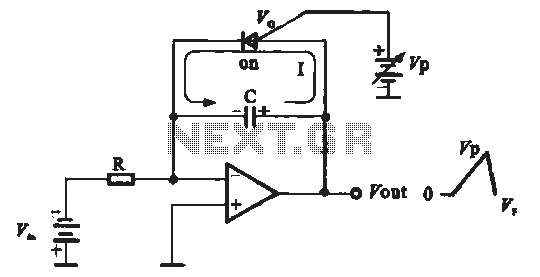
A sawtooth voltage-controlled oscillator operates by first generating a negative potential maximum at the output of the comparator. This output is then fed to the inverting input terminal through resistor R1, which is part of the relaxation oscillator. The...
This circuit is designed to indicate when room noise exceeds a predetermined threshold, utilizing a flashing LED to signal this condition. Three fixed noise levels are selectable: 50 dB, 70 dB, and 85 dB. The circuit employs two operational...
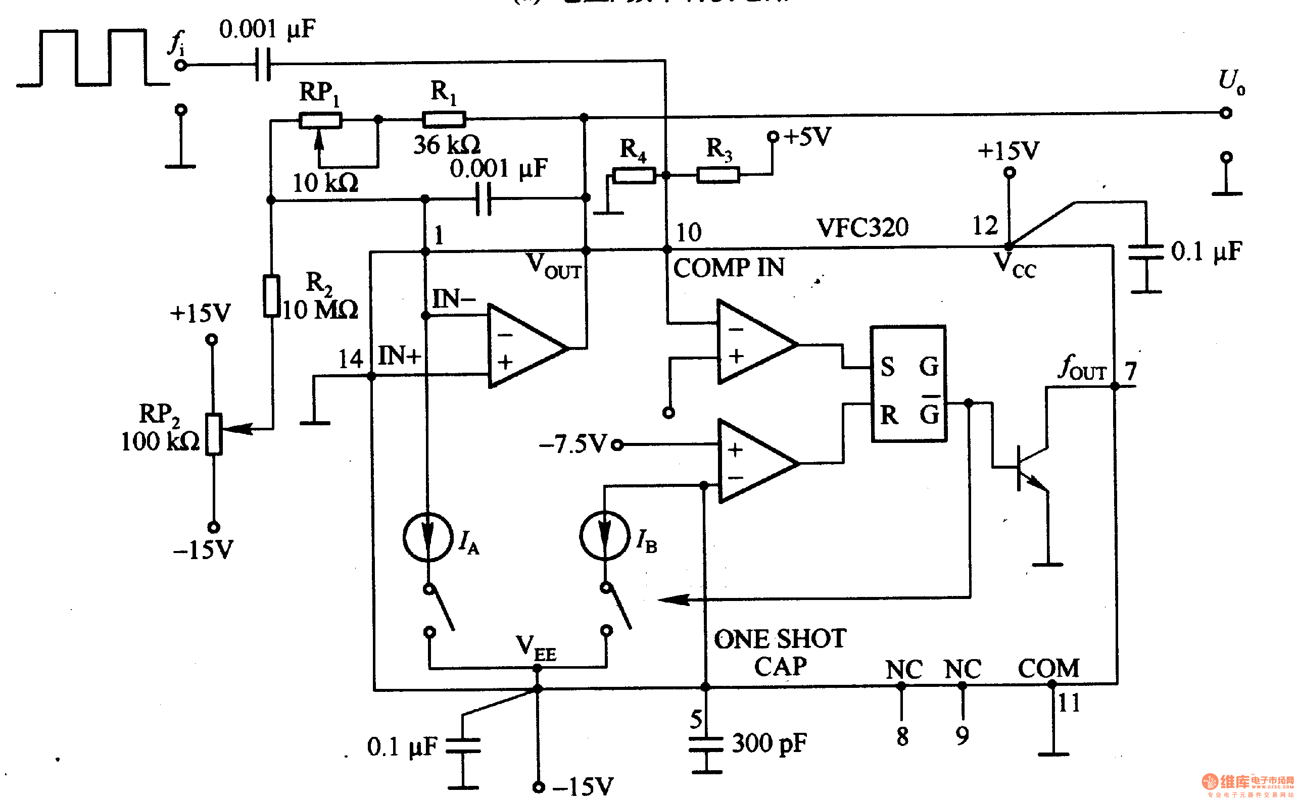
Figure 1-22 (a) illustrates a circuit that converts an input voltage of 0 to +10V (Ui) into a pulse with an output frequency ranging from 0 to 100kHz. In this configuration, pin 7 of the VFC320 is connected to...
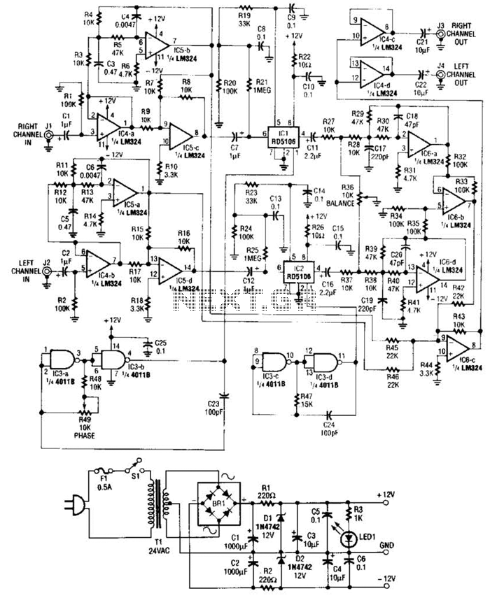
Right- and left-channel signals pass through buffer amplifiers C4-a and C4-b into the active crossover IG5. Low frequencies are directed to mixer IC6-c, while middle and high frequencies are sent to analog delay lines 1C1 and 1C2. The output...
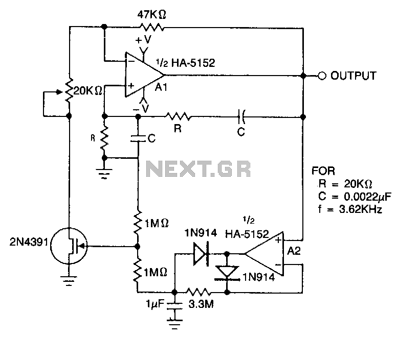
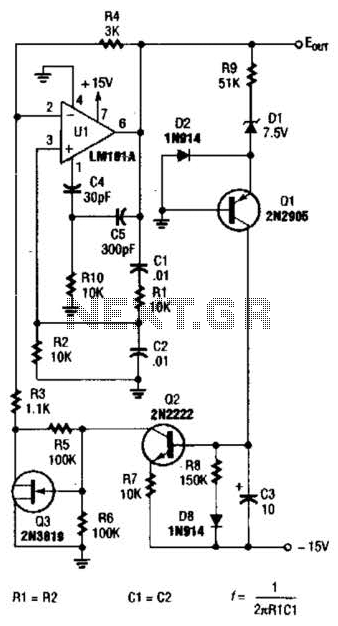
This circuit employs an HA-5152 dual operational amplifier and a field-effect transistor (FET) to create a low-voltage, low-power Wien bridge sine-wave oscillator. The frequency of oscillation is controlled by resistors and capacitors, while the FET functions as a voltage-controlled...
Warning: include(partials/cookie-banner.php): Failed to open stream: Permission denied in /var/www/html/nextgr/view-circuit.php on line 713
Warning: include(): Failed opening 'partials/cookie-banner.php' for inclusion (include_path='.:/usr/share/php') in /var/www/html/nextgr/view-circuit.php on line 713