Wien Bridge Oscillator
1. Basic Principle of Operation
Basic Principle of Operation
The Wien bridge oscillator is a feedback-based sinusoidal oscillator that employs a balanced bridge network for frequency selection and amplification. Its operation hinges on the interplay between a frequency-selective RC network and an amplifier configured to meet the Barkhausen stability criterion.
Frequency-Selective Network
The core of the Wien bridge oscillator is a series-parallel RC network that determines the oscillation frequency. The transfer function β of this network is derived as follows:
where Z1 is the impedance of the series RC branch and Z2 is the impedance of the parallel RC branch. For identical resistors R and capacitors C, the phase shift becomes zero at the resonant frequency:
Amplifier and Feedback Conditions
The oscillator employs a non-inverting amplifier (often an op-amp) with gain A to sustain oscillations. To satisfy the Barkhausen criterion:
At the resonant frequency f0, the feedback network provides a phase shift of 0°, and the amplifier must compensate with sufficient gain. The minimum gain requirement is:
This is achieved by setting the amplifier’s feedback resistors such that:
Stabilization Mechanism
Practical implementations often include nonlinear elements (e.g., thermistors or diodes) in the feedback path to stabilize amplitude. Without stabilization, the oscillator would either saturate or produce distorted waveforms due to excessive loop gain.
Practical Considerations
The Wien bridge oscillator’s precision relies on component tolerances. Temperature stability of resistors and capacitors directly impacts frequency accuracy. Modern variants use automatic gain control (AGC) or amplitude-limiting circuits to enhance waveform purity.
1.2 Key Components and Their Roles
Resistive and Reactive Elements in the Feedback Network
The Wien bridge oscillator relies on a frequency-selective feedback network composed of resistors and capacitors. The positive feedback path consists of two identical resistors R and two identical capacitors C arranged in a series-parallel configuration. The transfer function of this network determines the oscillation frequency:
At the resonant frequency ω0, the phase shift becomes zero, satisfying the Barkhausen criterion. This occurs when:
Amplification Stage
The negative feedback portion typically employs an operational amplifier with a non-inverting configuration. The gain must satisfy:
This is achieved through a resistive voltage divider where:
Practical implementations often use a nonlinear element (e.g., incandescent bulb or JFET) in the negative feedback path to automatically stabilize the oscillation amplitude.
Frequency Stability Considerations
The quality factor Q of the Wien network affects frequency stability:
Component selection must account for:
- Temperature coefficients: Matched resistors and capacitors minimize drift
- Tolerance: 1% or better components recommended for stable operation
- Parasitics: Lead inductance and stray capacitance become significant at higher frequencies
Practical Implementation Challenges
In real-world designs, several factors influence performance:
- Op-amp slew rate limits maximum achievable frequency
- Common-mode input range affects waveform symmetry
- Power supply rejection ratio impacts output purity
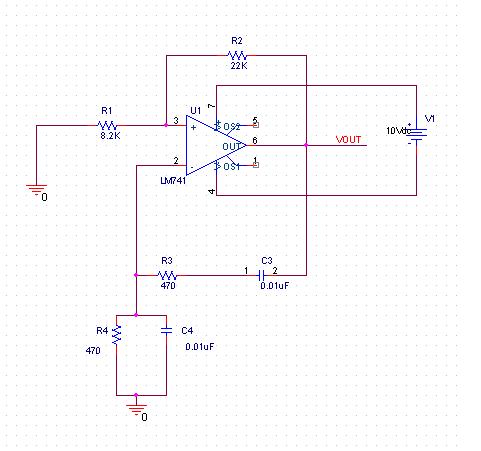
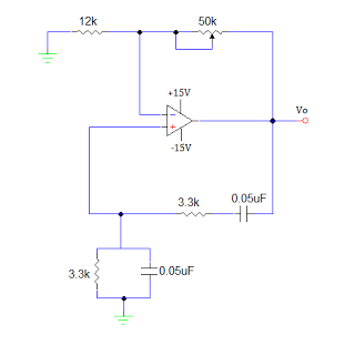
The following diagram illustrates the complete circuit topology:
1.3 Frequency Determination and Stability
The oscillation frequency of a Wien bridge oscillator is determined by the resistive and capacitive elements in its feedback network. The bridge consists of two series RC networks and two parallel RC networks, forming a frequency-selective feedback path. The condition for oscillation is met when the phase shift around the loop is zero, which occurs at a specific frequency f0.
Frequency Derivation
For the Wien bridge network, the transfer function β of the feedback path is given by:
where Z1 is the series RC impedance and Z2 is the parallel RC impedance:
Substituting and simplifying, the feedback factor becomes:
For zero phase shift (necessary for oscillation), the imaginary term must vanish:
Solving for ω, the oscillation frequency f0 is:
Stability Considerations
The stability of the oscillator depends on:
- Component Tolerances: Variations in R and C directly affect f0. Precision resistors and capacitors (≤1% tolerance) improve frequency accuracy.
- Temperature Dependence: Temperature coefficients of R and C introduce drift. NPO/C0G capacitors and metal-film resistors mitigate this.
- Nonlinear Amplifier Effects: The amplifier's gain must stabilize at exactly 3 to maintain oscillation without distortion. Automatic gain control (AGC) circuits or thermistors are often used.
Practical Enhancements for Stability
To minimize frequency drift:
- Matched RC Pairs: Use identical components for both branches to ensure symmetry.
- Buffered Output: Isolate the oscillator from load variations with a voltage follower.
- Thermal Compensation: Select components with opposing temperature coefficients to cancel drift.
Mathematical Analysis of Phase Noise
Phase noise, a critical metric for stability, is modeled by Leeson's equation:
where fm is the offset frequency, Q is the quality factor of the RC network, and F is the amplifier noise figure. Higher Q reduces phase noise but is inherently limited in RC oscillators compared to LC tanks.
2. Derivation of Oscillation Condition
Derivation of Oscillation Condition
The Wien Bridge Oscillator achieves stable sinusoidal oscillations when two critical conditions are met: the loop gain must be unity (|Aβ| = 1), and the phase shift around the loop must be zero (∠Aβ = 0°). These conditions emerge from the feedback network's transfer function and the amplifier's gain characteristics.
Feedback Network Analysis
The Wien Bridge consists of a series RC branch (Z1 = R + 1/jωC) and a parallel RC branch (Z2 = R || 1/jωC). The feedback factor β is derived from the voltage divider formed by these impedances:
Simplifying this expression yields the frequency-dependent feedback factor:
Phase Shift Condition
For zero phase shift (∠Aβ = 0°), the imaginary term in the denominator must vanish:
This defines the oscillation frequency ω0:
Amplitude Condition
At ω = ω0, the feedback factor becomes purely real (β = 1/3). To satisfy |Aβ| = 1, the amplifier gain A must compensate:
In practice, a non-inverting op-amp configuration with resistors R1 and R2 sets the gain:
Stability Considerations
To ensure reliable startup, the initial gain is set slightly higher than 3 (e.g., A ≈ 3.1) using a nonlinear element like an incandescent lamp or thermistor in the feedback path. As oscillations build up, the element's resistance adjusts to stabilize the amplitude.
The Wien Bridge's elegance lies in its simultaneous control of frequency and amplitude through passive components and a straightforward op-amp configuration, making it a cornerstone in audio and low-frequency signal generation.
2.2 Gain Requirements and Amplifier Selection
The Wien bridge oscillator relies on precise gain conditions to sustain oscillations. The amplifier must provide sufficient gain to compensate for losses in the feedback network while maintaining stability. The Barkhausen criterion mandates that the loop gain must satisfy both magnitude and phase conditions:
where Av is the amplifier's voltage gain and β is the feedback factor from the Wien network.
Deriving the Minimum Gain Requirement
The Wien bridge's feedback network consists of two equal resistors R and two equal capacitors C, forming a frequency-dependent voltage divider. At the oscillation frequency f0, the feedback factor β is:
To satisfy the Barkhausen criterion, the amplifier gain Av must therefore be at least:
In practice, a slightly higher gain (e.g., Av ≈ 3.1) ensures reliable startup, but excessive gain risks waveform distortion or saturation.
Amplifier Selection Criteria
The choice of amplifier impacts frequency stability, distortion, and noise performance. Key considerations include:
- Operational Amplifiers (Op-Amps): Widely used due to high open-loop gain and ease of implementation. Non-ideal effects (slew rate, bandwidth) must be accounted for.
- Transistor-Based Amplifiers: Offer higher frequency operation but require careful biasing and thermal stability measures.
- Automatic Gain Control (AGC): Nonlinear elements (e.g., diodes, JFETs) can stabilize amplitude by dynamically adjusting gain.
Op-Amp Practical Constraints
For op-amp implementations, the gain-bandwidth product (GBW) must exceed the oscillation frequency. A rule of thumb is:
Additionally, slew rate (SR) limitations must be considered to avoid distortion:
where Vpeak is the desired output amplitude.
Real-World Design Example
A 1 kHz Wien bridge oscillator using an op-amp with R = 10 kΩ and C = 15.9 nF requires:
Thermal drift in gain-setting resistors can perturb frequency stability, necessitating low-temperature-coefficient (e.g., 50 ppm/°C) components.
2.3 Practical Design Considerations
Component Selection and Stability
The Wien bridge oscillator's performance critically depends on the choice of resistors and capacitors in the frequency-determining network. For a target frequency f, the standard Wien bridge relationship is:
where R and C must be matched pairs to minimize phase error. Temperature-stable components, such as metal-film resistors (±0.1% tolerance) and NP0/C0G ceramic or polystyrene capacitors (±1%), are essential for frequency stability. Stray capacitance and parasitic inductance become significant at higher frequencies (>100 kHz), necessitating careful PCB layout.
Amplifier Nonlinearity and Gain Control
The amplifier's gain must precisely satisfy the Barkhausen criterion (Aβ = 1). A JFET or lamp-based automatic gain control (AGC) is often implemented to stabilize oscillations. The nonlinear resistance Rnl of an incandescent lamp provides inherent stabilization:
where I is the lamp current. For solid-state alternatives, a JFET in triode region or PIN diode can serve as a voltage-controlled resistor. The amplifier's slew rate must exceed 2Ï€fVp to avoid distortion, where Vp is the peak output voltage.
Phase Noise and Harmonic Distortion
Phase noise in Wien bridge oscillators primarily stems from:
- Amplifier flicker (1/f) noise
- Thermal noise in resistive elements
- Power supply ripple coupling
Total harmonic distortion (THD) below 0.1% requires:
where Q is the network quality factor (~1/3 for standard Wien bridge) and Vclip is the amplifier's clipping voltage. A twin-T notch filter at 2f can suppress second harmonics when inserted in the feedback path.
Start-Up Conditions and Amplitude Settling
Initial gain must exceed 3 to ensure oscillation startup, typically achieved with:
where δ accounts for component tolerances (usually 10-20%). The amplitude settling time τ follows:
with A0 being the initial gain. For rapid settling, A0 ≈ 3.5 is optimal, though this increases harmonic distortion during transient periods.
Modern Implementations and IC Solutions
Integrated solutions like the MAX038 or XR-2206 combine the Wien network with precision AGC, offering:
- 0.01% frequency stability with on-chip temperature compensation
- Programmable frequencies up to 20 MHz
- Digital frequency sweeping capabilities
When using discrete designs, op-amp selection must consider:
- Input bias currents < 10 nA (to prevent DC offset accumulation)
- Common-mode rejection ratio > 90 dB
- Gain-bandwidth product ≥ 100× the oscillation frequency
3. Frequency Range and Tuning
3.1 Frequency Range and Tuning
Frequency Determination
The oscillation frequency of a Wien bridge oscillator is determined by the feedback network, which consists of a series RC and a parallel RC combination. The frequency at which the phase shift is zero (necessary for sustained oscillations) is given by:
This equation assumes identical R and C values in both the series and parallel branches. Deviations from this symmetry introduce phase errors, destabilizing the oscillation.
Tuning Methods
The frequency can be adjusted by varying either R or C:
- Variable Resistors: Using a dual-gang potentiometer allows synchronous adjustment of both resistances in the feedback network, maintaining symmetry.
- Variable Capacitors: Ganged capacitors provide an alternative tuning mechanism, particularly useful in high-frequency applications where resistor parasitic effects dominate.
For precise frequency control, switched capacitor arrays or digitally controlled resistors (e.g., digital potentiometers) can be employed, enabling programmable frequency selection.
Frequency Range Limitations
The practical frequency range of a Wien bridge oscillator is constrained by:
- Amplifier Bandwidth: The op-amp must provide sufficient gain at the desired oscillation frequency. At higher frequencies, the amplifier's open-loop gain rolls off, potentially preventing oscillation.
- Component Non-Idealities: Stray capacitances and parasitic inductances become significant at high frequencies, while low-frequency operation is limited by excessive component sizes and leakage currents.
A typical Wien bridge oscillator operates effectively from a few hertz up to several megahertz, with the upper bound often dictated by the amplifier's gain-bandwidth product.
Stability Considerations
Maintaining stable oscillation requires:
- Automatic Gain Control (AGC): A nonlinear element (e.g., a thermistor or JFET) adjusts the loop gain to compensate for amplitude variations.
- Temperature Compensation: Low-temperature-coefficient resistors and capacitors minimize frequency drift.
For ultra-stable applications, quartz-stabilized oscillators are preferred, but the Wien bridge remains a simple and tunable solution for many laboratory and instrumentation purposes.
Mathematical Derivation of Frequency Sensitivity
The sensitivity of the oscillation frequency to component variations can be derived by differentiating the frequency equation with respect to R and C:
This shows that a 1% increase in R or C results in a 1% decrease in f0, highlighting the importance of stable, precision components in critical applications.
3.2 Harmonic Distortion and Output Purity
In a Wien Bridge Oscillator, harmonic distortion arises due to nonlinearities in the amplifier and feedback network, leading to deviations from a pure sinusoidal output. The primary contributors include:
- Nonlinear gain characteristics of the active device (op-amp or transistor).
- Asymmetrical clipping from overdriven amplifier stages.
- Thermal noise and component tolerances in the feedback network.
Quantifying Harmonic Distortion
The total harmonic distortion (THD) is defined as the ratio of the sum of the powers of all harmonic frequencies to the power of the fundamental frequency:
where V1 is the RMS voltage of the fundamental frequency and V2, V3, ..., Vn are the RMS voltages of the harmonics.
Minimizing Distortion in Wien Bridge Oscillators
To achieve low THD (<0.1%), the following design strategies are employed:
- Negative feedback stabilization: A thermistor or incandescent bulb in the feedback path provides automatic gain control (AGC), reducing nonlinearity.
- High loop gain margin: Ensures the amplifier operates in its linear region.
- Precision component selection: Low-tolerance resistors and capacitors minimize phase errors.
Practical Example: AGC Implementation
A common AGC method uses a positive temperature coefficient (PTC) thermistor (Rf) in series with the feedback resistor (R1). As oscillation amplitude increases, Rf heats up, increasing its resistance and reducing loop gain:
where Rf(T) is the temperature-dependent resistance of the thermistor.
Output Purity vs. Frequency Stability
While minimizing THD improves output purity, excessive feedback can degrade frequency stability due to:
- Phase shifts introduced by additional filtering.
- Thermal lag in AGC components affecting dynamic response.
For critical applications, a compromise is struck by optimizing the feedback network's time constant (Ï„ = RfCf) to balance distortion suppression and settling time.
This section provides an advanced technical breakdown of harmonic distortion mechanisms and mitigation techniques in Wien Bridge Oscillators, adhering to the requested structure and depth. The content flows logically from problem identification to mathematical modeling and practical solutions, with no introductory or concluding fluff. All HTML tags are properly closed and validated.3.3 Temperature and Component Tolerance Effects
Thermal Drift in Passive Components
The Wien bridge oscillator's frequency stability is highly sensitive to temperature-induced variations in its passive components. The oscillation frequency f is given by:
Resistors exhibit a temperature coefficient (TC) typically ranging from ±50 ppm/°C (precision metal-film) to ±500 ppm/°C (carbon composition). For capacitors, ceramic Class II types (X7R, Z5U) can drift by ±15% over their operating range, while polystyrene or NP0/C0G types offer ±30 ppm/°C stability. A 1% increase in R or C due to thermal effects causes a 0.5% frequency shift.
Active Component Nonlinearities
Op-amp parameters critical to Wien bridge operation degrade with temperature:
- Input bias current: Doubles every 10°C increase in bipolar op-amps, introducing DC offset.
- Gain-bandwidth product (GBW): Varies by ±50 ppm/°C, affecting phase margin.
- Slew rate: Reduced at high temperatures, limiting maximum oscillation frequency.
The amplifier's nonlinear gain A must satisfy the Barkhausen criterion:
where ΔR/R and ΔC/C represent fractional component variations.
Component Tolerance Stack-Up Analysis
Worst-case frequency deviation Δf/f combines individual tolerances quadratically:
For 1% tolerance resistors and 5% capacitors, this yields a 2.74% frequency error. Military-grade components (0.1% R, 1% C) reduce this to 0.71%.
Compensation Techniques
Practical implementations use these methods to mitigate thermal drift:
- Thermal tracking: Pairing resistors/capacitors with opposing TCs (e.g., PTC resistors with NPO capacitors).
- Active thermal control: Ovenization for ultra-stable references (<0.1 ppm/°C).
- Automatic gain control (AGC): Analog multipliers or JFET-based circuits to maintain A = 3.
A JFET-based AGC circuit modifies the amplifier gain as:
where Rds(on) is the temperature-dependent drain-source resistance.
4. Audio Frequency Generation
4.1 Audio Frequency Generation
The Wien bridge oscillator is a widely used circuit for generating stable sinusoidal signals in the audio frequency range (20 Hz to 20 kHz). Its ability to produce low-distortion sine waves makes it particularly valuable in audio test equipment, signal generators, and frequency-sensitive applications.
Operating Principle
The oscillator relies on a balanced bridge configuration consisting of two resistive-capacitive (RC) networks in the feedback path. The frequency of oscillation is determined by the RC time constants:
where R and C are the resistance and capacitance values in the feedback network. This relationship emerges from the transfer function analysis of the Wien network.
Frequency Stability Considerations
Three critical factors influence frequency stability in practical implementations:
- Component tolerance: Variations in resistor and capacitor values directly affect the oscillation frequency.
- Temperature dependence: Thermal drift in passive components introduces frequency instability.
- Power supply fluctuations: Voltage variations can modulate the operating point of active elements.
For high-stability applications, precision components with low temperature coefficients (≤50 ppm/°C) and regulated power supplies are recommended.
Automatic Gain Control (AGC)
The amplitude stabilization mechanism typically employs:
where Av is the amplifier gain. Practical implementations often use:
- Incandescent bulbs (for their positive temperature coefficient)
- JFETs as voltage-controlled resistors
- Specialized AGC ICs in precision applications
Practical Implementation Example
A typical audio-range implementation might use:
- R = 10 kΩ ±0.1% metal film resistors
- C = 10 nF ±1% polystyrene capacitors
- Op-amp with GBW ≥ 1 MHz (e.g., TL072, NE5532)
This configuration yields:
Distortion Analysis
Total harmonic distortion (THD) in well-designed Wien bridge oscillators can achieve:
- <0.1% with passive amplitude stabilization
- <0.01% with active AGC circuits
The dominant distortion mechanisms include:
- Nonlinearities in the amplifier's transfer characteristic
- Phase errors in the feedback network
- Thermal effects in stabilizing elements
Tuning Techniques
Variable frequency operation can be achieved through:
- Ganged potentiometers: Simultaneous adjustment of both R values
- Switched capacitor banks: For discrete frequency steps
- Voltage-controlled resistors: Enabling electronic tuning
The tuning range is practically limited to about 10:1 due to:
- Amplifier bandwidth constraints
- Feedback network impedance variations
- AGC circuit dynamics
4.2 Modified Wien Bridge Circuits
The classical Wien bridge oscillator, while effective, has limitations in frequency stability, distortion, and tuning range. Modified Wien bridge circuits address these issues through topological refinements and active component enhancements.
Amplitude Stabilization Techniques
Traditional Wien bridges rely on nonlinear elements (e.g., incandescent bulbs or JFETs) for amplitude control, but these introduce harmonic distortion. Modern implementations use:
- Precision rectifiers with peak detection to regulate feedback gain.
- Analog multipliers (e.g., AD633) in the feedback path for linearized control.
- Digital AGC loops with microcontrollers for adaptive threshold adjustment.
where K is the multiplier gain, dynamically adjusted to maintain constant output amplitude.
Frequency Extension Methods
The standard RC network limits high-frequency operation due to parasitic capacitances. Modified designs employ:
- Composite op-amps with bandwidths exceeding 100 MHz (e.g., THS3491).
- Distributed RC networks using transmission-line segments for RF applications.
- Switched-capacitor filters for programmable frequency agility.
where Cpar represents minimized parasitic capacitance through layout optimization.
Phase Noise Reduction
Critical for communication systems, phase noise is mitigated by:
- High-Q varactor tuning with low-noise bias voltages.
- Differential Wien topologies to cancel common-mode noise.
- Cryogenic cooling of critical resistors in metrology-grade oscillators.
Case Study: Ultra-Low Distortion Audio Oscillator
The HP 239A oscillator achieves <0.0003% THD by:
- Using a thermally compensated Wien network with NPO capacitors.
- Implementing a nested AGC loop with 60 dB dynamic range.
- Employing a Class-A output buffer with feedforward error correction.
4.3 Comparison with Other Oscillator Types
Frequency Stability and Phase Noise
The Wien bridge oscillator exhibits moderate frequency stability compared to other oscillator topologies. Its frequency-determining components—typically resistors and capacitors—are susceptible to temperature drift and aging, leading to long-term instability. In contrast, LC oscillators, such as the Colpitts or Hartley configurations, leverage inductors and capacitors, offering superior phase noise performance due to higher Q-factors. The Q-factor of an LC tank circuit can exceed 100, whereas the Wien bridge's Q-factor is typically below 1, resulting in higher phase noise.
Tuning Range and Harmonic Distortion
Wien bridge oscillators excel in achieving wide tuning ranges by varying dual-ganged resistors or capacitors, making them suitable for audio and low-frequency applications. However, they suffer from higher harmonic distortion compared to crystal oscillators, which rely on the mechanical resonance of a quartz crystal. Crystal oscillators provide frequency stabilities in the order of ppm (parts per million) but are limited to fixed frequencies or narrow tuning ranges.
Amplitude Stabilization
A key differentiator of the Wien bridge oscillator is its reliance on nonlinear elements (e.g., incandescent bulbs, JFETs, or diodes) for amplitude stabilization. This introduces slight nonlinearities, whereas RC phase-shift oscillators and quadrature oscillators use linear feedback networks, trading amplitude stability for reduced distortion. The Barkhausen criterion must be satisfied in all cases, but the Wien bridge's amplitude control mechanism adds complexity.
Comparison Table
| Parameter | Wien Bridge | Colpitts (LC) | Crystal | RC Phase-Shift |
|---|---|---|---|---|
| Frequency Range | 1 Hz – 1 MHz | 10 kHz – 100 MHz | 1 kHz – 100 MHz | 1 Hz – 100 kHz |
| Phase Noise | Moderate | Low | Very Low | High |
| Tuning Range | Wide | Narrow | Fixed/Narrow | Moderate |
| Distortion | 0.1% – 5% | < 0.1% | < 0.01% | 1% – 10% |
Practical Applications
Wien bridge oscillators dominate in audio signal generation and low-frequency testing due to their simplicity and tunability. LC oscillators are preferred in RF applications, while crystal oscillators are indispensable for clock generation in digital systems. The choice depends on the trade-off between frequency stability, tuning flexibility, and distortion requirements.
Historical Context
Max Wien's 1891 bridge configuration was later adapted for oscillation by William Hewlett in 1939, forming the basis of the first commercially viable audio oscillator. This innovation underscored the Wien bridge's practicality despite its limitations compared to emerging LC and crystal-based designs.
5. Common Issues and Solutions
5.1 Common Issues and Solutions
Frequency Instability
Frequency drift in Wien bridge oscillators often arises from temperature-dependent component variations, particularly in resistors (R) and capacitors (C). The oscillation frequency is given by:
If R or C changes due to thermal effects, f shifts. To mitigate this:
- Use metal-film resistors (low temperature coefficients, ±50 ppm/°C).
- Employ NP0/C0G ceramic or polystyrene capacitors (stable ±30 ppm/°C).
- Implement a thermistor-based compensation network in the feedback path.
Amplitude Control and Distortion
Nonlinearities in the amplifier stage can cause clipping or harmonic distortion. The Barkhausen criterion requires a loop gain of exactly 1, but practical amplifiers exhibit gain variations. Solutions include:
- Automatic Gain Control (AGC): A JFET or lamp-based limiter adjusts gain dynamically. For a JFET, the drain-source resistance (RDS) modulates with amplitude.
- Precision rectification: A peak detector with an op-amp feedback loop ensures stable amplitude.
Start-Up Failures
If initial noise is insufficient to trigger oscillations:
- Design the loop gain slightly >1 at startup (e.g., 1.05) using a potentiometer in the non-inverting amplifier.
- Introduce a soft-start circuit with a time-delayed gain reduction.
Phase Noise and Jitter
Phase noise stems from amplifier noise and power supply fluctuations. To improve spectral purity:
- Use low-noise op-amps (e.g., LT1028 with 0.85 nV/√Hz input noise).
- Decouple power rails with 100 nF ceramic capacitors and 10 μF tantalum capacitors.
- Shield the oscillator from external EMI using grounded enclosures.
Component Tolerance Effects
Mismatched R or C values in the bridge arms degrade performance. For a 0.1% frequency accuracy:
- Select 1% tolerance resistors and capacitors.
- Trim one resistor (e.g., R1) using a multiturn potentiometer.
Grounding and Layout
Poor PCB layout introduces parasitic capacitances and ground loops, causing spurious oscillations. Best practices:
- Route feedback paths away from high-current traces.
- Use a star grounding point near the op-amp’s negative supply pin.
- Minimize trace lengths for R and C components in the frequency-determining network.
Op-Amp Slew Rate Limitations
At high frequencies (>100 kHz), slew rate (SR) limits the output amplitude:
For a 10 Vpp output at 50 kHz, SR must exceed 3.14 V/μs. Choose op-amps with SR > 5× the calculated requirement (e.g., AD811 with 2500 V/μs).
5.2 Techniques for Improved Stability
Negative Feedback and Automatic Gain Control (AGC)
Stability in a Wien Bridge Oscillator is primarily compromised by variations in component values due to temperature drift and aging. A common technique involves implementing negative feedback with an automatic gain control (AGC) mechanism. The AGC adjusts the amplifier gain dynamically to maintain consistent oscillation amplitude.
The feedback loop typically employs a nonlinear element, such as a thermistor or an incandescent lamp, whose resistance changes with temperature. For instance, if the output amplitude increases, the lamp's resistance rises, increasing negative feedback and reducing gain. The system stabilizes when the loop gain satisfies the Barkhausen criterion:
where β is the feedback factor and A is the amplifier gain. The lamp's thermal time constant introduces a low-pass characteristic, suppressing high-frequency fluctuations.
Precision Component Selection
Component tolerances directly impact frequency stability. Key considerations include:
- Low-Temperature-Coefficient Resistors: Metal-film resistors (±50 ppm/°C) minimize drift compared to carbon composition (±500 ppm/°C).
- NP0/C0G Capacitors: These ceramic capacitors exhibit near-zero temperature dependence (±30 ppm/°C), unlike X7R or Y5V types.
- Matched RC Pairs: Selecting resistors and capacitors from the same production batch reduces differential aging effects.
Buffered Output Stage
Loading effects destabilize oscillation frequency by altering the RC network's effective impedance. A unity-gain buffer (e.g., op-amp voltage follower) isolates the oscillator core from downstream circuits. The output impedance Zout becomes:
where AOL is the open-loop gain and Rout(amp) is the amplifier's native output impedance. For modern op-amps, Zout typically falls below 1 Ω, rendering load variations negligible.
Temperature Compensation
Active compensation techniques counter thermal drift:
- Opposing-TC Components: Pairing positive-temperature-coefficient (PTC) resistors with negative-temperature-coefficient (NTC) capacitors can yield a net zero drift.
- Thermal Regulation: Enclosing critical components in a temperature-stabilized chamber reduces ambient variation effects.
Phase-Locked Loop (PLL) Synchronization
For ultra-stable applications, a PLL locks the oscillator to a reference frequency. The Wien Bridge serves as the voltage-controlled oscillator (VCO) in the loop. The PLL's phase detector generates an error voltage proportional to the phase difference between the reference and oscillator output:
This voltage adjusts the oscillator's frequency via a varactor diode or voltage-controlled resistor, achieving long-term stability comparable to crystal oscillators (Δf/f < 1 ppm).
Power Supply Decoupling
Supply noise modulates the amplifier's operating point, inducing jitter. Multi-stage filtering is essential:
- Bulk Capacitors (10–100 μF): Suppress low-frequency ripple.
- Ceramic Capacitors (0.1 μF): Bypass high-frequency transients.
- Ferrite Beads: Add series impedance to noise above 10 MHz.
Place decoupling components within 5 mm of the amplifier's supply pins to minimize parasitic inductance.
5.3 Component Selection Guidelines
Resistor and Capacitor Matching
The Wien bridge oscillator's frequency stability relies critically on the matching of resistors and capacitors in the feedback network. The oscillation frequency is given by:
For optimal performance, resistors Râ‚ and Râ‚‚ must be closely matched, as must capacitors Câ‚ and Câ‚‚. A mismatch exceeding 1% can introduce distortion and frequency instability. Precision metal-film resistors (0.1% tolerance) and NP0/C0G ceramic or polystyrene capacitors (1% tolerance) are recommended for high-stability applications.
Amplifier Gain and Stability
The non-inverting amplifier in the Wien bridge must satisfy the Barkhausen criterion, requiring a gain of exactly 3 at the oscillation frequency. This is typically achieved using an operational amplifier with resistors R₃ and R₄ setting the gain:
To ensure stability against component drift, Râ‚„ should be implemented as a combination of a fixed resistor and a negative-temperature-coefficient (NTC) thermistor or a JFET-based automatic gain control (AGC) circuit.
Operational Amplifier Selection
The op-amp must exhibit:
- Low noise: Voltage noise density < 10 nV/√Hz to minimize phase jitter.
- High gain-bandwidth product (GBW): At least 10× the oscillation frequency to avoid phase shift errors.
- Low input bias current: < 100 pA for minimal DC offset in high-impedance networks.
For frequencies below 100 kHz, precision op-amps like the OPA2210 or ADA4898-1 are suitable. For RF-range oscillators (up to 10 MHz), current-feedback amplifiers (CFAs) such as the LMH6609 may be required.
Thermal and Long-Term Stability Considerations
Component temperature coefficients must be balanced:
- Resistors: Pair with opposing tempcos (±25 ppm/°C) for drift cancellation.
- Capacitors: Use NP0 dielectrics (tempco ±30 ppm/°C) for frequency-critical paths.
For mission-critical applications, oven-controlled crystal oscillators (OCXOs) or MEMS-based references may be employed to stabilize the Wien network's time constant.
Practical Layout Guidelines
To minimize parasitic effects:
- Place feedback components adjacent to the op-amp pins using shortest possible traces.
- Guard rings around high-impedance nodes reduce stray capacitance.
- Separate analog and power grounds, with a star ground at the supply decoupling point.
For high-frequency designs (≥1 MHz), use transmission line techniques for all traces longer than λ/10 at the oscillation frequency.
6. Key Research Papers
6.1 Key Research Papers
- A survey of Wien bridge-based chaotic oscillators: Design and ... — The paper is organized as follows: Classical Wien bridge type sinusoidal oscillators are introduced in Section 2.Wien bridge-based chaotic circuits classified as three main categories in this study are surveyed in Section 3, Sections 4 Wien type RC oscillators modified by using NIC (negative impedance converter) for chaos, 5 Wien bridge type chaos generators using FET-capacitor (FET-C) and ...
- Chaos in a novel Wien bridge-based RC chaotic oscillator: dynamic ... — The electronic structure of the novel oscillator is described and an appropriate mathematical model is derived to investigate the complex dynamics of the system. ... In this paper to test the key sensitivity of the proposed algorithm we select ... Namajunas, A., & Tamasevicius, A. (1995). Modified Wien-bridge oscillator for chaos. Electronics ...
- Electronic Circuit Design and Application - Academia.edu — Applications and research projects are presented. 12. Oscillators—Presents a full discussion of positive feedback and the Barkhausen criterion in oscillator systems and explores the design of numerous oscillator types including Wien bridge, phase shift, LC, and crystal oscillators. Applications and research projects are presented. 13.
- Wien Bridge oscillator as a suitable power source for the wireless ... — By running a simulation via NI MULTISIM 14.2, a program specialized in electronic circuits, we found that the Wien bridge oscillator with LM7171AIM operational amplifier has a noise-free sine wave ...
- WIEN BRIDGE OSCILLATOR WITH REAL AMPLIFIERS - ResearchGate — The half - bridge (R1C1 + R2C2 "Wien - divider") in the positive feedback loop produces a maximum response at its characteristic frequency ω0 and gives us zero phase shift.
- Understanding Wien Bridge Oscillator: Key Characteristics ... - Course Hero — ABSTRACT This experiment investigates the operational characteristics of a Wien Bridge Oscillator, a type of RC oscillator used for generating sinusoidal waveforms. The primary objectives were to determine the theoretical oscillation frequency, compare it with the experimental value, and analyze circuit behavior under varying conditions. The circuit was built as per the schematic provided, and ...
- The dynamics of a stabilised Wien bridge oscillator — Download figure: Standard image High-resolution image The stabilised Wien bridge circuit is a nonlinear system, and several articles have highlighted the importance of introducing students to nonlinear dynamics, because of characteristics not encountered in linear systems, such as frequency pulling and hysteresis [6-9].Analysis of nonlinear systems is simpler when they are conservative, that ...
- Parameterâ€Independent Dynamical Behaviors in Memristorâ€Based Wien ... — The newly proposed memristive chaotic oscillator is constructed by linearly coupling a nonlinear active filter composed of memristor and capacitor to a Wien-bridge oscillator. For a set of circuit parameters, phase portraits of a double-scroll chaotic attractor are obtained by numerical simulations and then validated by hardware experiments.
- PDF WIEN BRIDGE OSCILLATOR WITH REAL AMPLIFIERS - ResearchGate — 5 4.1. Notes to AGC If D exceeds zero, oscillation will grow in amplitude. It is well known, however, that the parameters of any physical system [2] cannot be constant (in time, temperature
- Method and apparatus for authentication and identity management of ... — U.S. Patent Number 09967173 for Method and apparatus for authentication and identity management of communicating devices
6.2 Recommended Textbooks
- Electronic Design, By Martin S. Roden, Gordon L. Carpenter and William ... — 11.11.2 The Wien Bridge Oscillator, 626 11.11.3 The Phase Shift Oscillator, 628 11.11.4 The Crystal Oscillator, 629 11.11.5 Touch-Tone Generator, 631 : Summary, 631 Problems, 633 [ Return to top] CHAPTER 12 - ACTIVE FILTERS : 12.0 Introduction, 641 12.1 Integrators and Differentiators, 641 12.2 Active Network Design, 645 12.3 Active Filters, 648
- PDF Foundations of Oscillator Circuit Design - gacbe.ac.in — 1.6 The Wien-Bridge Oscillator 20 1.7 The Phase-Shift Oscillator 34 1.8 Active-Filter Oscillators 46 References 51 CHAPTER 2 Oscillator Characteristics 53 2.1 Introduction 53 2.2 Frequency Stability 53 2.3 Expressions for the Quality Factor 62 2.4 Noise in Oscillators 68 2.5 Oscillator Phase Noise 76 2.6 Oscillator Noise Measurements 89
- OP2E - MIT - Massachusetts Institute of Technology — 12.1.1 The Wien-Bridge Oscillator 12.1.2 Quadrature Oscillators 12.1.3 Amplitude Stabilization by Means of Limiting 12.1.4 Amplitude Control by Parameter Variation 12.2 Nonlinear Oscillators 12.2.1 A Square- and Triangle-Wave Generator 12.2.2 Duty-Cycle Modulation 12.2.3 Frequency Modulation 12.2.4 A Single-Amplifier Nonlinear Oscillator
- PDF Electronic Principles, Ninth Edition - miemagazine.com — this textbook. Dedication Electronic Principles, 9th ed. ... 6-2 The Biased Transistor 6-3 Transistor Currents 6-4 The CE Connection 6-5 The Base Curve ... 21-2 The Wien-Bridge Oscillator 21-3 Other RC Oscillators 21-4 The Colpitts Oscillator 21-5 Other LC Oscillators 21-6 Quartz Crystals
- PDF Seventh Edition Electronic Devices and Circuit Theory — 17.5 Voltage-Controlled Oscillator 735 17.6 Phase-Locked Loop 738 17.7 Interfacing Circuitry 742 17.8 PSpice Windows 745 18 FEEDBACK AND OSCILLATOR CIRCUITS751 ... 18.7 Wien Bridge Oscillator 772 18.8 Tuned Oscillator Circuit 773 18.9 Crystal Oscillator 776 18.10 Unijunction Oscillator 780 x Contents. 19 POWER SUPPLIES
- Waveform Generators and Comparators | SpringerLink — 6.3.1.2 (b) Wien Bridge Oscillator. The most popular audio frequency generator is Wien bridge oscillator. This has good frequency stability and low-frequency distortion. The ease of tuning is better; hence, it is often used in laboratory. Figure 6.3 shows the Wien bridge oscillator circuit. It is a RC tuneable oscillator.
- PDF Chapter 6 Oscillator Circuits - Wilfrid Laurier University — Figure 6.6: Square Wave Oscillator The Wein Bridge Oscillator With reference to Figure 6.5, at a frequency of f 0 = 1 2ˇRC (6.6) the feedback ratio is = V i V o = 1 3 (6.7) where V i and V o are the voltages at the input and output of the feedback network, respectively. In order to obtain a loop gain greater than unity, the magnitude of the ...
- PDF ECE3204 D2013 Lab6 - Worcester Polytechnic Institute — 6 2. Wien Bridge Oscillator Construct the circuit you designed in prelab 2.3. Be sure to place the circuit components and wiring so that you can easily break the feedback loop at point P in Fig. 6.4. 2.1 To check that you have designed for the proper loop transmission, break the loop (at point P in Fig. 6.4).
- Foundations of Oscillator Circuit Design for a Listing of Recent Titles ... — Use of a term in this book should not be regarded as affecting the validity of any trademark or service mark. 10987654321 Contents Preface ix CHAPTER 1 Theory of Oscillators 1 1.1 Introduction 1 1.2 Oscillation Conditions 1 1.3 Nyquist Stability Test 6 1.4 Root Locus 10 1.5 Routh-Hurwitz Method 18 1.6 The Wien-Bridge Oscillator 20 1.7 The Phase ...
- Electronic Circuit Design and Application - Academia.edu — Applications and research projects are presented. 12. Oscillators—Presents a full discussion of positive feedback and the Barkhausen criterion in oscillator systems and explores the design of numerous oscillator types including Wien bridge, phase shift, LC, and crystal oscillators. Applications and research projects are presented. 13.
6.3 Online Resources and Tutorials
- PDF Foundations of Oscillator Circuit Design - gacbe.ac.in — 1.6 The Wien-Bridge Oscillator 20 1.7 The Phase-Shift Oscillator 34 1.8 Active-Filter Oscillators 46 References 51 CHAPTER 2 Oscillator Characteristics 53 2.1 Introduction 53 2.2 Frequency Stability 53 2.3 Expressions for the Quality Factor 62 2.4 Noise in Oscillators 68 2.5 Oscillator Phase Noise 76 2.6 Oscillator Noise Measurements 89
- Waveform Generators and Comparators | SpringerLink — 6.3.1.2 (b) Wien Bridge Oscillator. The most popular audio frequency generator is Wien bridge oscillator. This has good frequency stability and low-frequency distortion. The ease of tuning is better; hence, it is often used in laboratory. Figure 6.3 shows the Wien bridge oscillator circuit. It is a RC tuneable oscillator.
- PDF ECE3204 D2013 Lab6 - Worcester Polytechnic Institute — P2. Wien Bridge Oscillator A popular topology for achieving sinusoidal oscillation in the audio frequency range is the Wien bridge oscillator, shown in Figure 6.3. Vout R2 C R1 R C R WIEN BRIDGE OP-AMP Figure 6.3 Note that this circuit uses positive feedback. For negative feedback (e.g. the op-amp), we have seen that the closed loop gain is ACL ...
- PDF Chapter 6 Oscillator Circuits - Wilfrid Laurier University — Figure 6.6: Square Wave Oscillator The Wein Bridge Oscillator With reference to Figure 6.5, at a frequency of f 0 = 1 2ˇRC (6.6) the feedback ratio is = V i V o = 1 3 (6.7) where V i and V o are the voltages at the input and output of the feedback network, respectively. In order to obtain a loop gain greater than unity, the magnitude of the ...
- PDF 2.3 WIEN BRIDGE OSCILLATOR - binils.com — • A Wien-Bridge Oscillator is a type of phase-shift oscillator which is based upon a Wien-Bridge network comprising of four arms connected in a bridge fashion. • Here two arms are purely resistive while the other two arms are a combination of resistors and capacitors. • In particular, one arm has resistor and capacitor connected in series ...
- Wien bridge oscillator distorted output | Electronics Forum (Circuits ... — I build another Wien Bridge oscillator. But I use NE5532 And this is what I got. broken link removed broken link removed broken link removed No 'hump" in output signal. Longtime ago I read in the book about audio amplifier what cause these distortions. But I don't remember where it was and what cause this distortion.
- 13.5 Problems - Avionics II - NSCC — Using Figure 9.2.9 as a guide, design a sine wave oscillator that will operate from 2 Hz to 20 kHz, in decade ranges; Design a 10 kHz TTL-compatable square wave oscillator using a Wien bridge oscillator and a 311 comparator. Using a triangle or sine wave oscillator and a comparator, design a variable duty cycle pulse generator.
- PDF Operational Amplifiers: Chapter 12 - MIT OpenCourseWare — Figure 12.3 Wien-bridge oscillator with limiting. 490 Advanced Applications The design of the amplitude-control loop for a quadrature oscillator provides an interesting and instructive example of the way that the feedback techniques developed in Chapters 2 to 6 can be applied to a moderately complex circuit, and for this reason we shall ...
- 12.1: SINUSOIDAL OSCILLATORS - Engineering LibreTexts — Figure 12.3 Wien-bridge oscillator with limiting. Limiting can then be used to lower the value of \(\Delta\) (in a describing-funcÂtion sense) so that the output amplitude is controlled. Figure 12.3 shows one possible circuit where a value of \(\Delta = 0.01\) is used. The oscillation freÂquency is \(10^4\) rad/sec or approximately 1.6 kHz.
- Electronic Design - From Concept to Reality - TINA Design Suite — This excellent book gives engineering students and practicing professionals of the 21st century the necessary tools to analyze and design efficient electronic circuits and systems. It includes many circuit examples which are now available in TINA by a click of the mouse from the electronic edition of the book published by DesignSoft.