
Window comparator

The circuit utilizes two integrated circuits (ICs): the LM319 and the TL081. The LM319 is a high-speed voltage comparator that can be configured for various threshold detection applications. It provides the necessary functionality to set and adjust the upper and lower threshold voltages accurately. The TL081, on the other hand, is a low-noise JFET-input operational amplifier that may be employed for signal conditioning or buffering within the circuit.
The design typically incorporates a dual comparator configuration using the LM319, where each comparator is assigned to monitor one of the threshold levels. The outputs from these comparators can be connected to digital logic circuits or microcontrollers to indicate whether the input voltage is within the specified window range. The adjustable thresholds allow for flexibility in applications, enabling the circuit to accommodate different voltage levels based on the requirements of the specific application.
The circuit may also include potentiometers for fine-tuning the threshold levels, facilitating easy adjustments by the user. Additionally, the digital outputs can be used to drive LEDs or other indicators, providing a visual representation of whether the input signal is within the defined window range.
Overall, this configuration provides a robust solution for applications requiring precise voltage level monitoring and control, making it suitable for various electronic projects and systems.This circuit provides independently adjustable upper and lower threshold settings, and has sign, in window range, in upper window, and in lower window digital outputs. ICs used: LM319, TL081. 🔗 External reference
Related Circuits
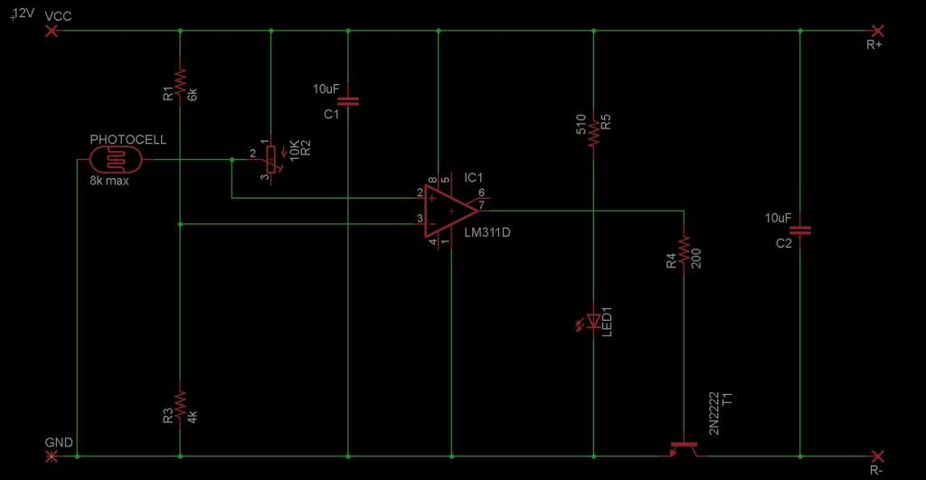
The circuit is designed to sense ambient light levels and activate lights when it is dark. A prototype was successfully built on a breadboard using an LM324 comparator, various resistors, a trimmer resistor, and a photocell. Subsequently, a PCB...
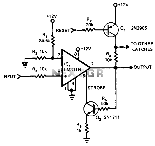
The main advantage of this circuit, in comparison to other comparators, is its capability to latch once the input surpasses a specified threshold level. When the input goes beyond this threshold, the output of the LM311N rises. This change...
This application note outlines the design of a PC-based, 14-bit data acquisition system. It adopts a systematic approach, incorporating all essential components: analog, digital, hardware, and software. The document elaborates on each phase, emphasizing the testing of individual systems...
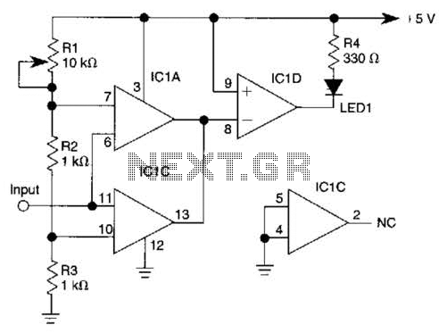
IC1-c functions as a non-inverting comparator, while IC1-a operates as an inverting comparator. Potentiometer R1 and fixed resistors R2 and R3 create a voltage divider chain that provides slightly different voltages to the two comparators. These voltages establish the...
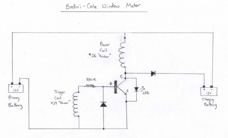
Experimenting with the window motor reveals that its power is derived from the minimal current required, which is an independent variable from the strength of the permanent magnets on the rotors. The true power is found in the magnetic...
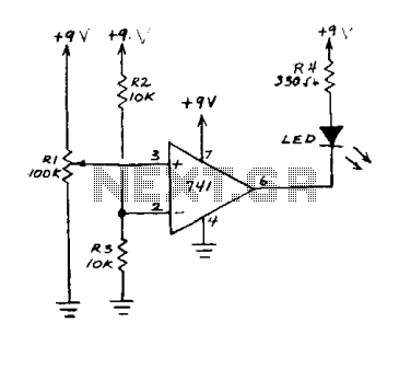
This circuit is an operational amplifier (op-amp) configuration that operates without a feedback resistor. The junction point of resistors R2 and R3 establishes the reference voltage. When the input voltage, determined by resistor R1, falls below this reference voltage,...