
Winds from the 555 programmed
The wind speed programmable circuit operates by integrating several critical components to achieve precise control over fan speed. The step-down rectifier serves as the initial stage, converting AC voltage to a stable DC voltage, which is essential for the subsequent control circuits. The core timing mechanism utilizes the 555 timer IC, which is renowned for its versatility in generating precise time delays and oscillations. The configuration of resistors and capacitors surrounding the 555 timer determines the timing intervals, allowing for a customizable range of wind speeds.
The multi-stage cycle timing circuit employs a series of 555 timers (IC1, IC2, IC3, and IC4), each configured in a monostable mode to create a cascading effect. As each timer completes its set delay, it triggers the next stage, leading to a sequential activation of the output devices. This design ensures that the fan operates in a rhythmic pattern, mimicking natural wind variations, which can enhance comfort in various applications.
The phase shift control circuit, consisting of BG2 to BG4, provides additional modulation of the output voltage to the fan motor. By adjusting the potentiometers (W5, W7, and W8), the user can influence the duration of the voltage application to each phase, thereby controlling the speed and behavior of the fan motor. This capability allows for fine-tuning of the wind speed to suit specific environmental conditions or user preferences.
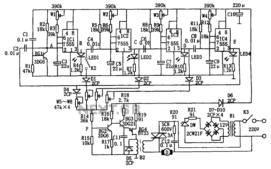
Overall, the design of this wind speed programmable circuit emphasizes flexibility and user control, making it suitable for applications where variable air movement is desired. The integration of timing circuits with phase control enhances the functionality, providing a sophisticated solution for managing fan speeds in various settings. As shown in FIG wind speed programmable circuit. The circuit consists of step-down rectifier circuit, a multi-stage cycle timing circuit, phase shift control circuit, thyristor control circuit. Wherein the circuit is a buck rectifier provides a DC voltage across the controller.Multi-level loop by the timing circuit 555 as the core component of the four single stable circuit. Just power on, the start-up circuit R1, C1 and BG1 composition generates a negative pulse applied to IC1 (555) of the trigger terminal ( feet), so that the delay circuit consists of IC1, W1, R3, C3 composed happen set, the output high.
Corresponding to the delay time td1 1.1 (Rw1 + R3) C3, illustrated parameters corresponding time is about 0.6 to 10 seconds. In the meantime, C3 is charged when the voltage on C3 charge to make IC1 foot to reach 2/3VDD when, IC1 reset occurs, a low level output by C4 3 feet, after R5 differential added to IC2 feet, IC2 corresponding timing circuit occurs due feet set, output high to low.
IC3, IC4 state change of the same. When the output from the IC4 3 feet high into low (delay expires) when it is fed back to the trigger terminal of IC1 feet, repeat the process in order to achieve multi-heap Fan thin 5 Mi Van braid barium meal Bru joint of bones intestinal worm ED1, LED2, LED3, LED4 sequentially lit, and at any one time only one light.Phase shift control circuit consists of BG2 ~ BG4 composition. Cycle timer IC2, IC3, IC4 output through W5, W7, W8 applied to the control circuit, adjusting W5, W7, W8, may be changed accordingly t2, t3, t4 period applied to each voltage value BG2.
When the minimum potentiometer resistance, that is applied to the BG2 maximum input voltage, this time near both ends of the motor voltage of 220V, the fan has a maximum wind speed; maximum when the resistance of each potentiometer, the corresponding minimum fan wind speed. When each potentiometer W5 ~ W8 tune in a different location, because each level is inconsistent period, the motor speed operation, to achieve a similar effect of natural wind.
Adjust W1 ~ W4, for different lengths of time can be controlled to achieve the rate of change of wind speed rhythm to adjust.
Related Circuits

This is a simple 555 timer circuit suitable for oscillating applications. To slow down the strobe effect, replace the 220 µF capacitors with 1000 µF capacitors. For a faster strobe effect, use a 150 µF capacitor. Additionally, R1 can...
The lantern control circuit allows for the management of 30 outputs through an external driver circuit, specifically designed for water sports or large decorative lantern applications. The circuit features a control pulse generator, which regulates the lights, and an...
This is a driving relay circuit utilizing a 555 integrated circuit (IC). The circuit is designed to control a relay and prevent the 555 IC from becoming unresponsive by employing inductive feedback. The coil is safeguarded. The driving relay circuit...
Most recent cars are equipped with a significant amount of electronics, including ABS brake systems, engine control with injection calculators, airbag activation, and various comfort functions. One such function, which is often overlooked, is the automatic activation of windshield...
The circuit of a burglar alarm utilizing IC timer 555/556 functions as a security measure to prevent unauthorized entry into a premises. The alarm generates a loud sound when a thin wire connecting resistor R1 with pin 4 of...
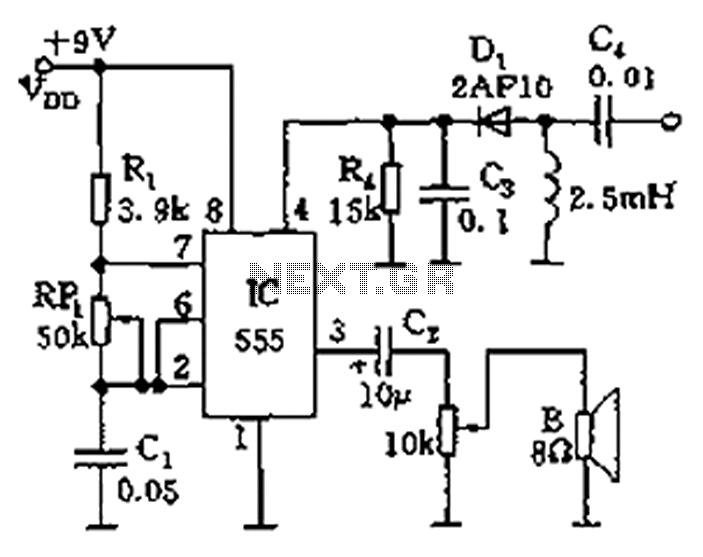
The circuit features a 555 timer integrated circuit along with components R1, RP1, C1, and others, which together form an audio oscillator. The frequency of the oscillator is determined by the formula f = 1.44 / ((R1 + 2...