
Wireless Communication Hobby Projects
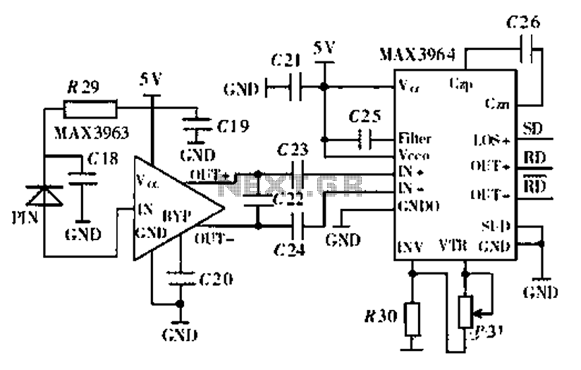
The described homebrew signal meter utilizes the RSSI output from the National LMX2240 Intermediate Frequency Receiver to gauge signal strength in a Symphony-based wireless network. The RSSI output, which varies with signal strength, is captured during the receive phase, necessitating the use of a modulation meter to average the resulting voltage spikes. This process provides a practical means of assessing signal quality without the need for expensive commercial equipment.
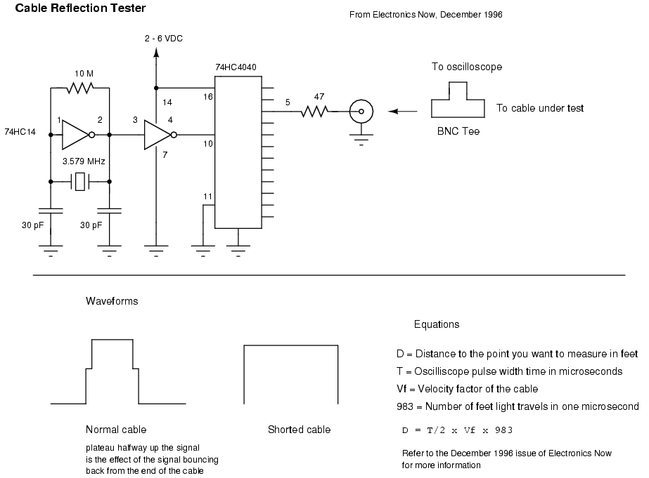
Construction of attenuator pads allows for the simulation of signal loss, which is essential for accurate testing of wireless links under realistic conditions. The option to utilize commercial attenuators or high-loss cables provides flexibility in achieving desired attenuation levels. The cable reflection tester serves as a valuable tool for diagnosing coaxial cable integrity, allowing for the identification of shorts and impedance mismatches, critical for maintaining optimal signal integrity in network setups.
For wireless link analysis, the modification of low-cost audio/video transmitters presents an accessible method for evaluating the performance of 2.4 GHz links in various environments. The spectrum analyzer project offers further insights into frequency behavior, enhancing the understanding of signal characteristics across a range of frequencies. These tools collectively contribute to a comprehensive approach to signal strength testing and analysis in wireless communication systems.Another method of testing the received signal strength on a Symphony based wireless network is with a homebrew signal meter. The National LMX2240 Intermediate Frequency Receiver has a certain pin called "RSSI Out". RSSI stands for relative signal strength indicator and supplies a voltage output that is an indication of the received signal strength.
O n a weakly received signal the voltage output of the RSSI is small and on a strong signal it`s large. Unfortunately, this output is only on during the receive portion and off during transmit. This makes the RSSI output look like a series of spikes. To average out these spikes you can use a very common piece of test equipment on any good technician`s bench: a modulation meter.
What You say Modulation meters convert received audio signals into a DC voltage indication of modulation, if you input the RSSI spikes into the meter (and readjust its ballistics) you will get a poor man`s signal meter. The meter I use is based on the Mark Weiss modulation meter. You can also make some attenuator pads to help simulate real life signal loss when testing your wireless network links.
If you wish, you can order commercial inline attenuators from Mini-Circuits that will handle 2 Watts of power, DC - 18 GHz, and have built in SMA connectors for around $37 a piece. You may also combine attenuator pads to increase the overall attenuation. It`s also possible to use a long length of high-loss cable, such as RG-174, as an attenuator. Higher wattage resistors will handle higher RF power, though the frequency response will suffer due to parasitic reactances.
Lower wattage resistors will handle higher power if applied in small durations (milliseconds), like which is commonly found in most wireless network applications. Here is a schematic for a homebrew cable reflection tester from the December 1996 issue of Electronics Now.
It`s very useful for checking coax cable runs for shorts or even impedance mismatches. It works by sending a pulse down the cable, then checking the return signal on an oscilloscope. You can then determine the distance to a short or impedance mismatch using simple distance = time x speed equations. Be sure to divide your time by 2, and take in account your cable`s velocity factor. Here is a schematic for a homebrew cable reflection tester from the December 1996 issue of Electronics Now.
It`s very useful for checking coax cable runs for shorts or even impedance mismatches. It works by sending a pulse down the cable, then checking the return signal on an oscilloscope. You can then determine the distance to a short or impedance mismatch using simple distance = time x speed equations. Be sure to divide your time by 2, and take in account your cable`s velocity factor. One of the coolest things to do is 2. 4 GHz wireless link analysis using those $99 wireless audio/video transmitters from Radio Shack (part number 15-1971).
They transmit about 1 mW on the frequencies of 2. 411, 2. 434, 2. 453, and 2. 473 GHz. They can even be modified for an external antenna output jack, just like the Symphony, and can also have their output RF power increased to around 60 mW. Refer to this site for a how-to and schematic for that modification. You can then use a portable CD player and portable audio amplifier/speaker to verify that a 2. 4 GHz link is possible in the enviroment you`re testing. It`s not an entirelly accurate analysis do to the narrow bandwidth of audio, but should still be useful.
Here is a homebrew spectrum analyzer you can build using an old VCR tuner module. Frequency coverage will be from around 80 MHz to 920 MHz and varies slightly with tuner manufacturer. It will also require an old oscilloscope that is capable of X/Y mode with DC input and a receiver which can tune around 47 MHz AM and can also be modified to tap its AM detector.
It`s even possible to downconvert a 2. 4 GHz signal down to VHF frequencies using a slightly mod 🔗 External reference
Related Circuits
Here's a way to get a short range bidirectional RF (Radio Frequency) channel on a microcontroller, using the controller's tristatable I/O pins and on-chip comparator with a few passive components. The range with the firmware and simple I came...
This alarm circuit is an anti-theft wireless alarm that can be used with any vehicle operating on a 6 to 12-volt DC supply system. The mini VHF FM radio-controlled transmitter is installed in the vehicle at night when it...
Nowadays, every institution requires automation. As part of college automation, a project has been developed titled "Voice Interactive System for College Automation." This project enables users to quickly access student attendance and marks through a telephone line without the...
An 18-year-old electrical engineering student, Chris Rieger, has been developing his levitating light bulb project, aptly named the LevLight Project, for approximately six months. Recently, he shared images and a video of the project, which gained significant attention on...
Ethernet is the most widely used networking technology, known for its high reliability, informative media, and ease of expansion and updates. It is commonly utilized in businesses, schools, and various other fields. According to the IEEE802.3 Ethernet specification, the...
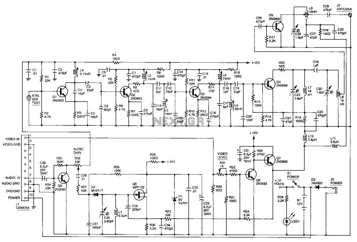
This high-performance video camera link transmits signals from a video camera to a VCR or from a VCR to televisions throughout a home. The initial stage of the RF chain is a crystal-controlled oscillator, Q1, operating at a frequency...