
wireless digital code lock with a status display
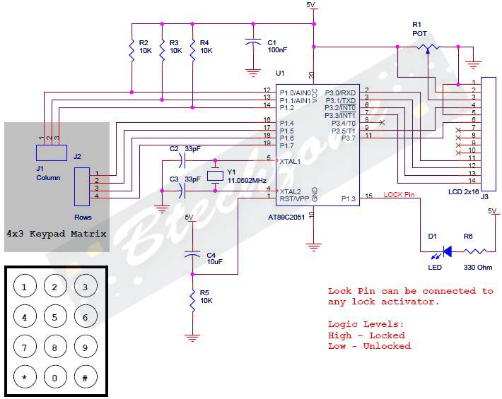
The Digital Code Lock project employs the AT89C2051 microcontroller, which is a popular choice for embedded systems due to its compact size and versatility. The system architecture includes an LCD for user interaction, providing visual feedback for the entered codes and system status. The 4x3 keypad allows for efficient input of the numeric codes, with a simple layout that ensures ease of use.
The design incorporates a robust security mechanism, utilizing a 5-digit user code and a 10-digit master code to enhance security against unauthorized access. The use of a master password allows for administrative control over the user codes, enabling the user to change their access credentials securely.
The microcontroller processes the input from the keypad, validating it against the stored codes. If the correct user code is entered, the system activates the lock, indicated by the LED. In case of incorrect attempts, the system can be programmed to implement a timeout or lockout feature to deter brute force attacks.
The software component of the project is written in C, ensuring that the logic for handling keypad inputs, LCD display updates, and security checks is efficiently executed. The provision of both C and hex files allows for flexibility in programming the microcontroller, catering to users who may want to modify or extend the functionality of the system.
Overall, the Digital Code Lock project serves as an excellent example of integrating hardware and software components to create a secure access control system, showcasing the capabilities of microcontrollers in modern electronic applications.Warning: Missing argument 2 for wpdb::prepare(), called in /home3/nithish/public_html/btechzone. com/wp-content/plugins/sharebar/sharebar. php on line 112 and defined in /home3/nithish/public_html/btechzone. com/wp-includes/wp-db. php on line 992 Warning: Missing argument 2 for wpdb::prepare(), called in /home3/nithish/public_html/btechzone. com/wp-con tent/plugins/sharebar/sharebar. php on line 124 and defined in /home3/nithish/public_html/btechzone. com/wp-includes/wp-db. php on line 992 Here is a project called Digital Code Lock using AT89C2051 ². LCD is used for display and a keyboard is used to input the keys. This project source code is written in C. Both the C files and hex files are given for download. This a simple project with efficient hacking prevention from Brute Force etc. The basic user lock is of 5 Digits and Master Lock is of 10 digits so its not easy for an intruder to break the lock unless you keep the code simple. The input is taken from a 4G—3 Keypad (please see the schematic for more information) and Display the user input on a 2G—16 LCD.
A pin is assigned as output for activating and deactivating the lock. For demonstration i have connected an LED to that pin. The user has two options either he/she can use its own 5 digit code or use the default 5 digit code. If user has to do setup his own code, then he has to enter 12345 ³ and press #`. After this. controller will ask for 10 Digit master password which is preprogrammed in the controller. Entering master lock, user can enter the new 5 digit code for the lock and press #` to save it. Keypad has 12 keys (4G—3) starting from 1, 2, 3, 4, 5, 6, 7, 8, 9, *, 0, # (please see the schematic for layout). Numeric keys are used for entering numbers. *` is used as the Cancel key and #` is used as the Enter key. 🔗 External reference
Related Circuits
A simple whole house FM transmitter circuit diagram and description. Operating power is a 1.5V battery of any type. This circuit is able to transmit at a distance of 30 meters. The whole house FM transmitter circuit operates on a...
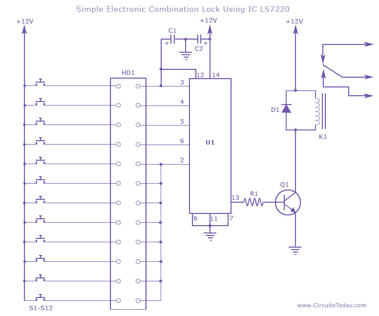
This circuit diagram illustrates a simple electronic combination lock utilizing the IC LS7220. It is designed to activate a relay for controlling any device (on & off) when a specific combination of four digits is entered. The circuit operates...
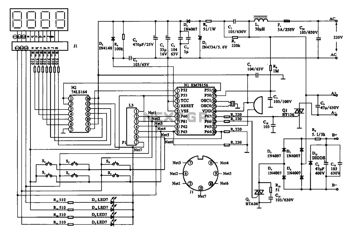
The display circuit is utilized in a typical digital massager. At the heart of the control circuit is the microprocessor EM78156, which receives manual operation instructions. It triggers two transistors to supply voltage to the DC motor (A +,...
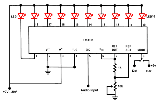
This is a simple audio sound level LED display circuit diagram. The circuit is entirely based on a single integrated circuit, the LM3915 from National Semiconductor. The LM3915 is a monolithic integrated circuit that displays the audio sound level...

The concept involved removing the center page from a magazine and cutting it into four pieces to create a card suitable for a filing system. The front side of each card provided connections to the integrated circuit (IC), while...

Unfortunately, this circuit only provides 1.8V signals and requires a converter to interface with the 3.3V signals used by most raw LCDs. The main component is the TFP101A, which was obtained as a free sample from Texas Instruments. The...
Warning: include(partials/cookie-banner.php): Failed to open stream: Permission denied in /var/www/html/nextgr/view-circuit.php on line 713
Warning: include(): Failed opening 'partials/cookie-banner.php' for inclusion (include_path='.:/usr/share/php') in /var/www/html/nextgr/view-circuit.php on line 713