
Wireless remote control switch circuit 5
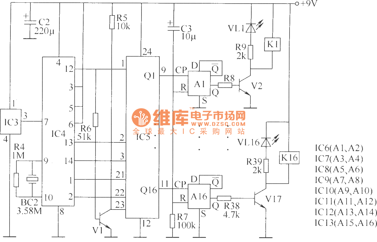
The wireless remote control transmitter circuit is designed to facilitate the transmission of control signals over a distance, typically using infrared or radio frequency technology. The control buttons S1 to S16 allow the user to input commands, which are processed by the DTMF encoder integrated circuits (IC1 and IC2). These encoders convert the button presses into a series of dual-tone multi-frequency signals, which are then transmitted wirelessly.
Resistors R1 to R3 serve various functions, including current limiting for the control buttons and setting the biasing levels for the integrated circuits. The choice of 1/4W carbon film resistors ensures that the circuit operates efficiently while maintaining thermal stability. Capacitor C1 is used for decoupling and filtering, which helps stabilize the power supply to the DTMF encoder and other components, reducing noise and improving performance.
The regulator diode VS is essential for providing a stable voltage to the circuit, ensuring that all components operate within their specified voltage ranges. The crystal oscillator BC1 is responsible for generating the clock signal required by the DTMF encoders, ensuring precise timing for signal transmission.
Overall, this wireless remote control transmitter circuit is a well-structured assembly of components that work together to enable effective and reliable remote control functionality. Each component plays a crucial role in ensuring that the circuit operates as intended, providing a user-friendly interface for controlling devices wirelessly.Wireless remote control transmitter circuit is composed of control buttons S1 ~ S16, resistors R1 ~ R3, capacitor C1 regulator diode VS, crystal oscillator BC1, DTMF encoder IC IC1 and IC2 wireless remote control transmitter integrated circuit components. It is shown as above. Components selectionR1, R2 and R4, R6 ~ R39 use 1/4W carbon film resistors.. 🔗 External reference
Related Circuits
This simple microcontroller circuit regulates a servo motor based on a 3-state switch. The servo motor functions as an actuator with three positions. It consists of three wires: one for VCC, one for ground, and a third for position...
The circuit operates based on a desired temperature setting. It can be utilized for various applications, such as turning on a fan at a specified temperature or activating an emergency temperature alarm. The power supply for the circuit can...
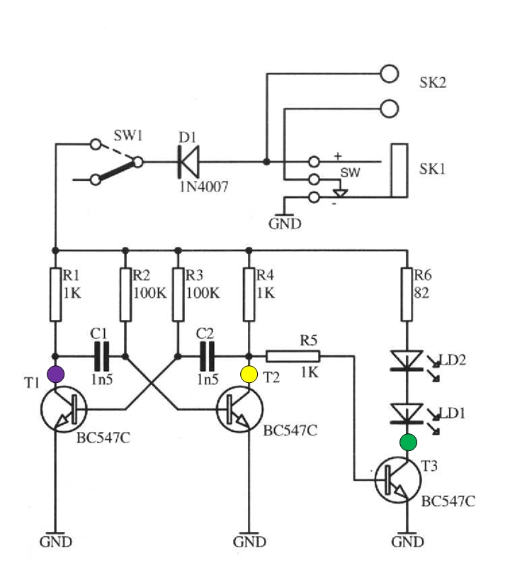
The schematic circuit presented below illustrates an infrared transmitter. The infrared beam is emitted in a nearly line-of-sight manner towards another device equipped with an infrared receiver. The displayed waveforms represent the output voltages from two intermediate stages (purple...
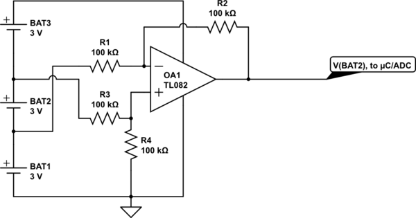
Utilize a high-performance microcontroller (Piccolo TMS320F28035, 12-bit resolution, +/- 4 LSB offset, +/- 60 LSB gain) to measure the voltage across stacked battery cells and control related analog electronics for charge equalization. The microcontroller will also save data in...
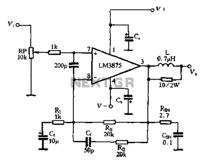
The 875T and LM3876T are high-performance 40W power amplifier integrated circuits (ICs). They operate within a frequency range of 20Hz to 20kHz with a continuous average power output under an 8-ohm load and exhibit a distortion level of only...
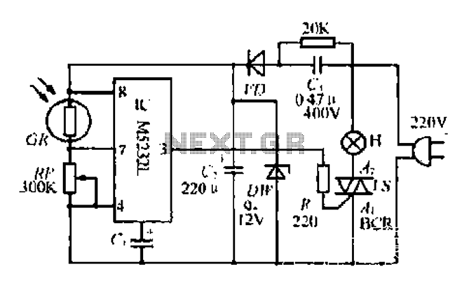
The DW L11 capacitor steps down voltage into the Jenru half crossing according to Yin electrical specifications. After receiving power at the bin CI SH output terminal, it regulates the voltage to liVI/r j, ensuring a right cut in...