
Wireless-telephone-eavesdropper
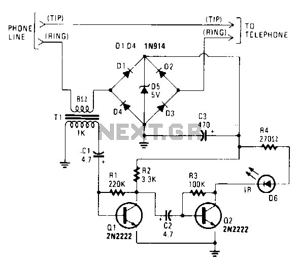
The IR transmitter connects to a telephone circuit and transmits both sides of all telephone conversations to any line-of-sight location within 40 feet. No power is drawn from the central office, as long as all phones remain on-hook. The current flows through the phone and back to the central office, thereby keying their equipment. The telephone line is tapped by connecting the IR transmitter circuit in series with either the tip or ring. When the telephone is off-hook, current will flow through the diode bridge polarity protector and supply power for the IR transmitter. The audio information from the phone is extracted from the line by transformer T1. The 1000-0 winding of the transformer connects to a two-stage transistor audio amplifier/modulator. A 2000-ohm potentiometer could be added to the input of the two-stage amplifier to control the modulation level, and another potentiometer could be added in place of R3 to adjust the IR's idle current.
The IR transmitter circuit is designed to facilitate wireless communication by capturing audio signals from a telephone line and converting them into infrared signals for transmission. The system operates by integrating with the existing telephone infrastructure without drawing power during idle states, thus maintaining the functionality of the phone line.
The circuit begins with the connection of the IR transmitter to the telephone line, where it is integrated in series with either the tip or ring wire. This configuration allows the circuit to monitor the audio signals while ensuring that the central office remains unaware of the additional load. The IR transmitter remains dormant when the telephone is on-hook, preventing any interference with normal operation.
When the telephone is taken off-hook, a current flows through the diode bridge polarity protector, which ensures that the IR transmitter receives the correct polarity and is powered adequately. The audio signals from the telephone line are extracted through transformer T1, which isolates the circuit from the telephone line while providing the necessary voltage levels for processing.
The output from the transformer feeds into a two-stage transistor audio amplifier/modulator. This amplifier boosts the audio signals for modulation, enabling effective transmission over infrared. The addition of a 2000-ohm potentiometer at the input allows for fine-tuning of the modulation level, enhancing the clarity and strength of the transmitted signal. Furthermore, an additional potentiometer can be introduced in place of resistor R3 to adjust the idle current of the IR transmitter, ensuring optimal performance and power efficiency.
Overall, this IR transmitter circuit provides a practical solution for remotely monitoring telephone conversations, with careful consideration of power management and signal integrity. The design allows for easy adjustments to accommodate various operational conditions, making it versatile for different applications.The IR transmitter connects to a telephone cir cuit, and transmits both sides of all telephone conversations to any line-of"sight location, within 40 feet. No !fOWer is taken from the central office, as long as all phones remain on-hook. The current flows through the phone and back to the central office, thereby keying their equipment.
We tap into the telephone line by connecting the IR transmitter circuit in series with either the tip or ring. When the telephone is off-hook, current will flow through the diode bridge polarity protector and supply the power for the IR transmitter. The phone. s -audio information is taken off the line by transformer Tl. The 1000-0 winding of the transformer connects to a two-stage transistor audio amplifier/modulator. A 2000-fl potentiometer could be added to the input of the two-stage amplifier to control the modulation HANDS-ON ELECTRONICS Fig.
102-25 level, and another potentiometer could be added in place of R3 to adjust the IR"s idle current. 🔗 External reference