
Wireless-video-camera-link
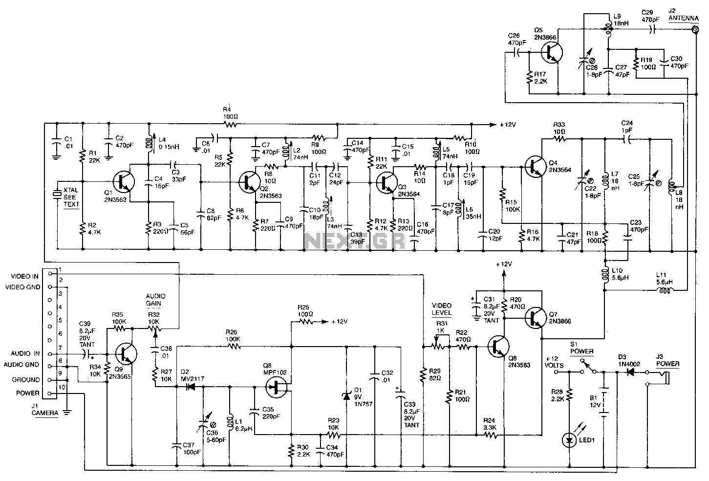
This high-performance video camera link transmits signals from a video camera to a VCR or from a VCR to televisions throughout a home. The initial stage of the RF chain is a crystal-controlled oscillator, Q1, operating at a frequency range of 60 to 65 MHz, which is one-eighth of the final output frequency. The oscillator generates a signal of approximately +6 dBm (4 mW), which drives three stages of frequency doublers. The combined effect of these doublers increases the input frequency by a factor of eight, resulting in a nominal final output frequency of 500 MHz. Double-tuned circuits are employed between each stage to minimize spurious outputs that could lead to unwanted interference. The video input signal from the VCR or video camera is fed into a video modulator, Q6 and Q7, which combines the video signal with the +12 V power supply for the final doubler, Q4, and the output amplifier, Q5. This modulation technique is akin to the method used in conventional AM radio transmitters. The video modulator has a nominal bandwidth of five MHz. The audio input is connected to QS, functioning as a VCO with a nominal frequency of 4.5 MHz, producing the modulated sound carrier. For simplicity, QS operates as a free-running oscillator, as achieving the ±25 kHz frequency deviation required would be challenging with a crystal-controlled oscillator. Furthermore, most television sound systems can tolerate a ±10 kHz deviation in the sound carrier frequency without significant distortion, simplifying the required circuitry. The kit is available from North Country Radio, P.O. Box 53, Wykagyl Station, NY 10804.
The circuit described operates as a comprehensive video and audio transmission system, effectively transmitting signals wirelessly between video sources and display devices. The crystal-controlled oscillator (Q1) is pivotal, as it establishes the fundamental frequency that will be manipulated throughout the circuit. By generating a signal in the 60 to 65 MHz range, the oscillator provides a stable and precise frequency reference necessary for the subsequent frequency doubling stages.
The use of frequency doublers is critical in achieving the desired output frequency of 500 MHz. Each doubler stage increases the frequency, ensuring that the final output is suitable for transmission over typical RF channels. The double-tuned circuits between these stages serve to filter out unwanted harmonics and spurious signals, enhancing the overall signal integrity and reducing the risk of interference with other electronic devices.
In the video modulation process, Q6 and Q7 work together to encode the video signal onto the RF carrier. This method of modulation is essential for maintaining the quality of the transmitted video, ensuring that it can be accurately decoded by receiving devices. The nominal bandwidth of five MHz for the video modulator indicates that the system is designed to handle standard video formats, accommodating the necessary data rates for clear transmission.
The audio section, governed by the voltage-controlled oscillator (QS), introduces another layer of complexity. Operating at a nominal frequency of 4.5 MHz, this section modulates the audio signal onto a separate carrier frequency, allowing for simultaneous transmission of both audio and video signals. The design choice of using a free-running oscillator simplifies the circuit while still meeting the performance requirements of typical television sound systems.
Overall, this schematic represents a sophisticated approach to wireless video and audio transmission, combining several techniques to ensure high-quality signal delivery across a home entertainment setup. The components selected and their configurations reflect a careful consideration of both performance and practicality, making this system suitable for a variety of applications in consumer electronics.This high-performance video-camera link transmits signals from your video camera to your VCR, or from your VCR to TVs throughout your home. The first stage of the rf chain is a crystal-controlled oscillator, Q1, with a frequency of 60 to 65 MHz, which is one-eighth of the final output frequency.
The oscillator produces a signal of about +6 dBm (4 mW) that drives three stages of frequency doublers. The combined action of those doublers multiplies the input frequency by eight for a final output frequency of (nominally) 500 MHz.
Double-tuned circuits are used between each stage to help reduce spurious outputs that might cause unwanted interference. The video input signal from your VCR, video camera, etc. drives a video modulator, Q6 and Q7, that adds the video signal to the +12 V fine supplying power to the final doubler, Q4, and the output amplifier, Q5.
That method of modulation is similar to the way a conventional AM-radio transmitter is modulated. The video modulator has a nominal bandwidth of five MHz. The audio input is applied to QS, which operates as a VCO running at a nominal frequency of 4;5 MHz to produce the modulated sound carrier. For simplicity, QS is a free-rurming oscillator, since the ±25 kHz frequency deviation that is required would be very difficult to produce at that frequency with a crystal-controlled oscillator.
Besides, most TV sound systems will accept a ±10 kHz error in the sound-carrier frequency without producing undue distortion, and that greatly simplifies the circuitry required. The kit is available from North Country Radio, P.O. Box 53, Wykagyl Station, NY 10804. 🔗 External reference