
Wiring diagram for 3 way switch
This circuit operates by sampling the audio signal from the speaker outputs of an audio amplifier. The audio signal is fed into a rectifier circuit, which converts the AC signal into a corresponding DC voltage that represents the audio volume level. This DC voltage is then used to control the brightness of the LEDs.
To implement this, a bridge rectifier can be used to ensure that the signal is always positive, regardless of the audio waveform's polarity. Following the rectification, a low-pass filter may be employed to smooth out the fluctuations in the audio signal, providing a stable voltage that corresponds to the average volume level.
The variable resistor (10k ohm VR) serves as an adjustable gain control, allowing the user to calibrate the sensitivity of the circuit to the audio input. This adjustment is crucial to ensure that the LEDs respond appropriately to the volume levels, preventing them from being overly dim or excessively bright.
For the LED configuration, a series of LEDs can be arranged in parallel, each connected to the output of the rectifier and filter circuit. The number of LEDs illuminated can correspond to the volume level, with more LEDs lighting up as the audio signal increases. Different colors can be used to create a visually appealing display, enhancing the overall experience.
To ensure proper functionality, it is important to consider the current-limiting resistors for each LED to prevent damage due to excessive current. The selection of these resistors will depend on the forward voltage of the LEDs and the supply voltage used in the circuit.
In summary, this project combines audio signal processing with visual display technology, allowing for an engaging interaction between sound and light. The design is straightforward, making it accessible for hobbyists and electronic enthusiasts looking to enhance their audio experiences visually.I like to see lights move to music. This project will indicate the volume level of the audio going to your speakers by lighting up LEDS. The LEDS can be any color so mix them up and really make it look good. The input of the circuit is connected to the speaker output of your audio amplifier. You want to build two identical units to indicate both right and left channels. The input signal level is adjusted by the 10k ohm VR. 🔗 External reference
Related Circuits
The sensor operates on the principle that at high temperatures (200 to 800 °F), the temperature of the sensor varies with the thermal conductivity of gas, leading to changes in the resistance of the platinum resistor wire. In the...
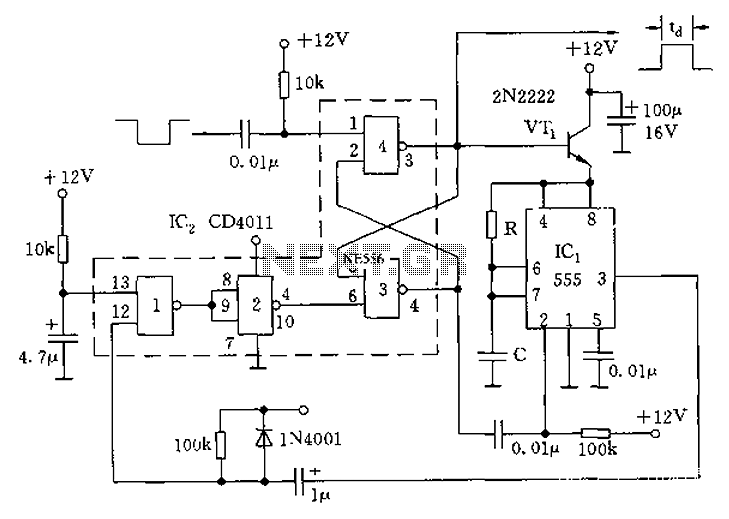
The circuit consists of four 2-input NAND gates and a CMOS CD4011 type 555 timer, allowing for either a static or high-time period output while maintaining minimal power consumption. Additionally, the circuit features a 3-door and 4-door composition RS...
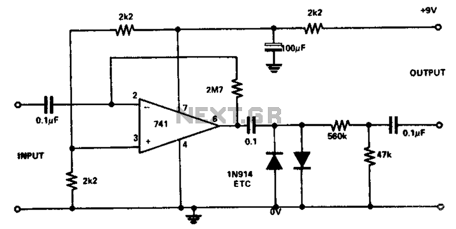
The circuit utilizes the 741 operational amplifier, which has a maximum gain of 20,000. However, the design achieves a gain of 2.7 million, resulting in output distortion. This distortion is attributed to noise effects. Two clamping diodes are employed...
The CT Scanner, short for computed tomography scanner, was invented in 1970, building on prior advancements in dedicated minicomputers. A high DC voltage is applied to the capacitors as X-rays enter the system. The chamber ionizes the xenon gas,...
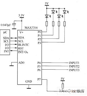
The main technical characteristics of the MAX7316 include a 400 kbps, 2-wire serial interface with a voltage tolerance of 5.5V. The operating voltage ranges from 2V to 3.6V. It features 8-bit PWM control for white LED brightness, with global...
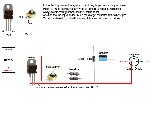
Construct a custom burning laser. This guide outlines a proper method for building a burning laser, ensuring a long lifespan for the device. There are multiple advantages to this approach over simply connecting the laser diode to batteries, which...
Warning: include(partials/cookie-banner.php): Failed to open stream: Permission denied in /var/www/html/nextgr/view-circuit.php on line 713
Warning: include(): Failed opening 'partials/cookie-banner.php' for inclusion (include_path='.:/usr/share/php') in /var/www/html/nextgr/view-circuit.php on line 713