
With NE555 making push-button delay section lamp circuit
The NE555 timer is a versatile integrated circuit widely used in various timing applications, including delay circuits, oscillators, and pulse generation. In this specific configuration, the NE555 operates in monostable mode, where it generates a single output pulse in response to a trigger input. When the push-button switch SB is pressed, it triggers the NE555, causing the output to go high and energizing the relay K. This action not only closes the circuit but also initiates the timing period during which the lamp H remains lit.
The charging of capacitor C3 through resistor R2 establishes the timing interval. The time duration for which the output remains high can be calculated using the formula T = 1.1 * R2 * C3, where T is the time in seconds. This relationship highlights the direct proportionality between the resistance, capacitance, and timing duration. The choice of components must therefore consider both the desired timing period and the characteristics of the NE555 timer.
The relay K serves as an electromechanical switch that allows the control of higher power loads, such as the lamp H, without subjecting the NE555 or other low-power components to high currents. The self-locking mechanism facilitated by the relay ensures that once the lamp is turned on, it remains illuminated until the timing cycle is completed, providing convenience and energy efficiency.
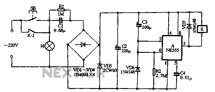
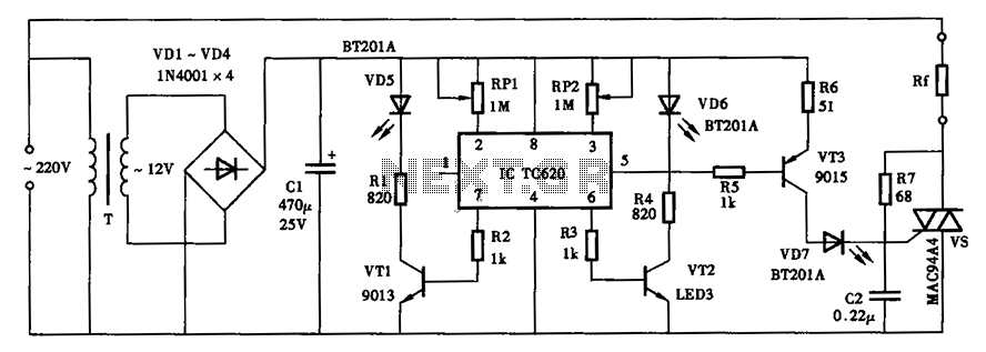
In summary, the NE555 push-button delay lamp circuit effectively combines timing and relay control to create a practical solution for managing lighting applications. The careful selection of resistors and capacitors allows for customization of the delay period, making it adaptable for various scenarios. The circuit is robust, simple to construct, and provides a reliable means of controlling lighting with minimal energy consumption during inactive periods.With NE555 making push-button delay section lamp circuit shown in Figure 3-5, the circuit from when base integrated circuits, power supply and road relay control circuit of several components. Usually the key switch SB and normally open relay contacts kl unit open, so H is not bright lights, do not eliminate the entire circuit consumes energy. Turn on the lights when needed, just click the switch SB, H lamp immediately energized to emit light.
Meanwhile 220V AC by the capacitor C1 buck, VDl ~ VD4 rectifier diodes, voltage regulator VD5 and filter capacitor C2, the output DC voltage of about 12V. In this case charging the capacitor C3 through the resistor R2, since the voltage across the capacitor can not change suddenly, so the base circuit A illustrates the value end of the 6 foot was high time base circuit is reset, its output 3 pin output low, the relay K was electric pull station, close contacts kl close the circuit self-locking, so in this case, although the switch SB tripped lamp H still remain alight.
As the capacitor C3 charging constantly, triggering end timebase circuit A 2 foot level declining, when the supply voltage drops 1/3, flip the circuit is set , the output terminal 3 feet high output, relay K Loss electric release, contacts kl jump lift self-locking, the circuit returns to the original state before starting the lamp H goes out. At this time when the C3 charge stored in the base circuit through the internal resistance of the diode VD6 vent discharge, can prepare for the next turn on the lights for the delay.
That time delay circuit H lamp lighting time depends only on the charge R2 and C3 is a constant electricity when asked, regardless of other factors, the power supply voltage. Illustrated using data every time pressing SB, lights about two to three minutes, For an extension of time can increase the R2 (or C3) values; on the contrary, reduced R2 (or C3) values.
Related Circuits
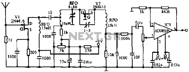
The image illustrates the JFET VHF band super-regenerative receiver circuit. It features high discharge tubes V1 and V2, which serve as the super-regenerative detector tubes. IC1 functions as a low-frequency amplifier. The circuit exhibits a sensitivity of better than...
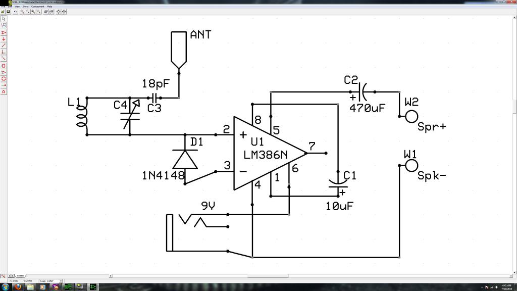
Initially, the individual has limited experience in electronics. They constructed a crystal radio circuit using components salvaged from a non-functional radio, including an LM386N audio amplifier. A crystal radio circuit is a simple radio receiver that operates without the need...
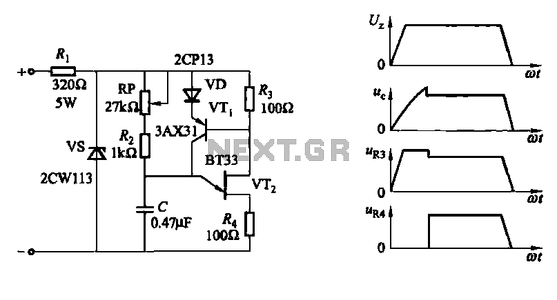
A conventional single junction transistor trigger circuit is limited to producing narrow pulses due to the rapid turn-off characteristics of the single-junction transistor. To address this limitation, a PNP transistor is added to the single-junction transistor trigger circuit, which...
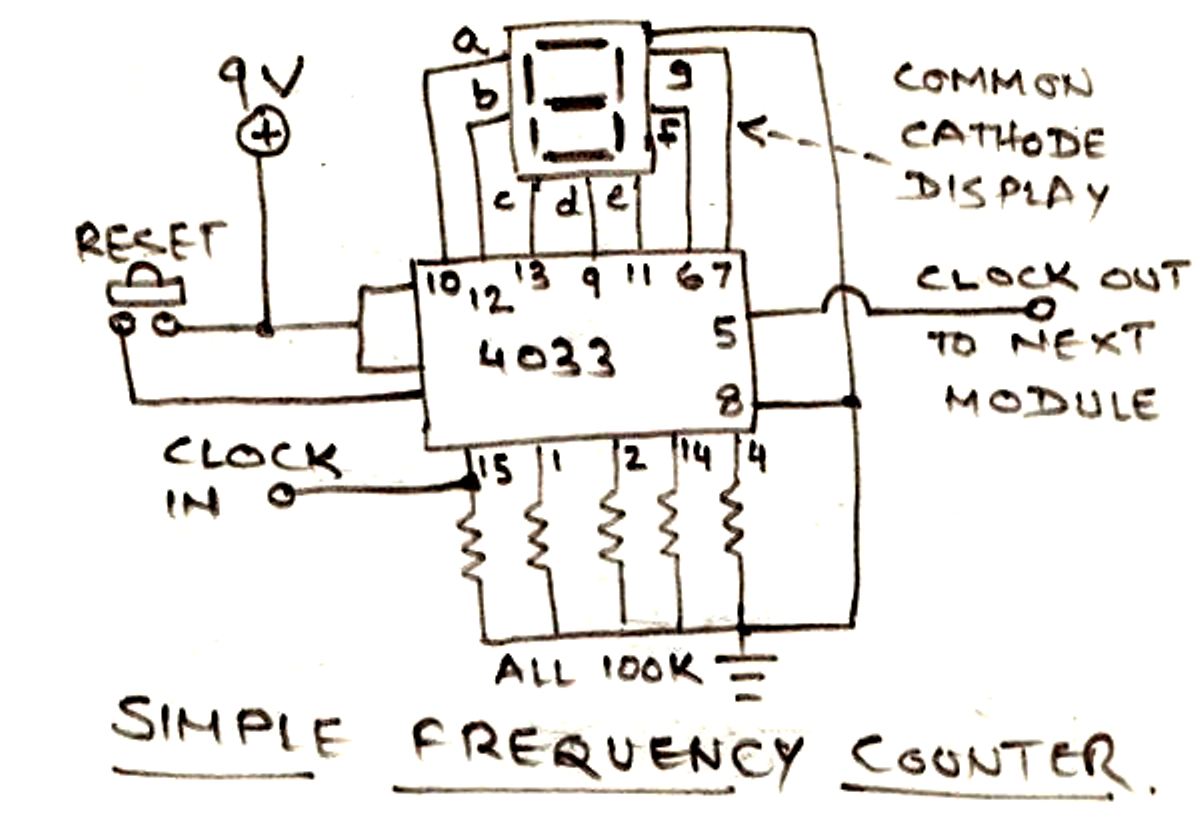
The circuit illustrated below is designed for measuring frequency in Hertz (Hz). It is straightforward to construct, utilizing a single IC 4033 and a common cathode display as the main components. For measuring higher frequencies, typically in the range...
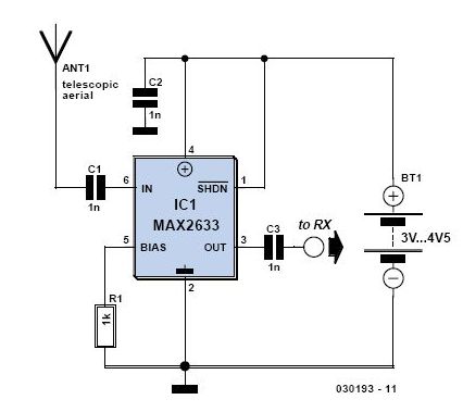
This is a preselector circuit designed for shortwave (SW) receivers, specifically a do-it-yourself (DIY) high-frequency preselector. The circuit employs a modern low-capacitance MOSFET with two gates, which generates a negative inverse reaction through an uncoupled source resistor. When applied...
The thermostat can be set, and it specifies the lower limit of the circuit diagram. The thermostat in the circuit is a critical component used to regulate temperature by controlling the heating or cooling system. It operates by comparing the...