
Xenon Flasher

The voltage doubler circuit is designed to convert an AC input voltage into a higher DC output voltage, effectively doubling the voltage available for charging the capacitor. The 60 µF capacitor serves as the energy storage element, accumulating charge until it reaches a voltage sufficient to trigger the SIDAC device. The SIDAC, once activated, allows current to flow through the Xenon lamp, producing a brief and intense flash of light.
The flash rate of the circuit is controlled by the resistors R4 and R5, along with the capacitor C4. These components form an RC timing circuit that dictates how long the capacitor takes to charge and subsequently discharge. Adjusting the values of R4 and R5 will alter the time constant of the circuit, thereby changing the frequency of the flashes emitted by the Xenon lamp.
In practical applications, this circuit can be employed in photographic flash units, strobe lights, or other lighting systems requiring high-intensity bursts of light. The choice of a Xenon lamp is crucial due to its ability to produce a bright flash with a very short duration, making it ideal for applications where quick illumination is necessary. The SIDAC device ensures reliable triggering at a specified voltage, contributing to the overall efficiency and performance of the circuit. Using a voltage-doubler supply, this circuit charges a 60-/aF capacitor and discharges it through a Xenon lamp. The SIDAC dev ice is manufactured by Motorola. It is a two-terminal device that breaks over at a specified voltage. R4, R5, and C4 determine the flash rate. 🔗 External reference
Related Circuits
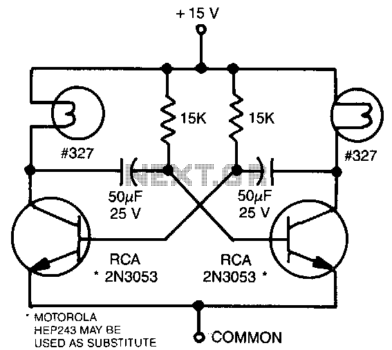
This astable multivibrator utilizes incandescent lamps instead of collector load resistors. The lamps flash on and off alternately. The circuit operates as an astable multivibrator, which is a type of oscillator that continuously switches between its high and low states...
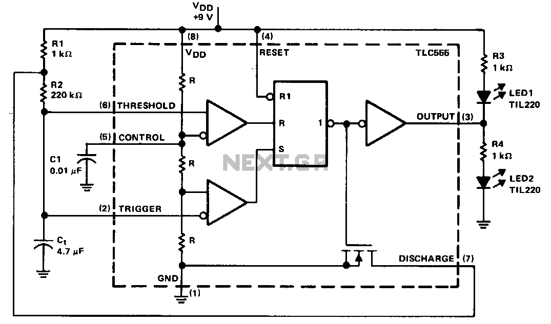
The timing components are R1, R2, and C1. C1 is a bypass capacitor used to reduce the effects of noise. At start-up, the voltage across C1 is less than the trigger level voltage (1/3 Vcc), causing the timer to...
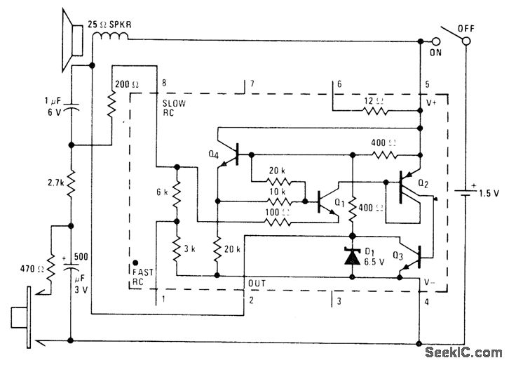
A low-drain circuit powered by a 1.5-V cell utilizes the National LM3909 flasher IC to simulate a fire-alarm siren. Pressing a button generates a rapidly increasing wail, with the tone decreasing in frequency once the button is released. The...
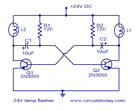
The circuit operates on 24V DC and is designed to alternately flash two 24V bulbs. It functions as an astable multivibrator with a frequency of 1Hz and a duty cycle of 50%. The lamps to be flashed are connected...

This simple LED light flasher project utilizes a Hex Inverter 74C04 integrated circuit (IC) to generate a square wave pulse, which is employed to alternately turn two LEDs on and off. The circuit design comprises a 74C04 Hex Inverter IC,...

This is a flasher circuit that directly derives power from AC to produce brilliant flashes at a rate of one flash per second. It utilizes a DIAC as the main element. The flasher circuit operates by converting alternating current (AC)...
Warning: include(partials/cookie-banner.php): Failed to open stream: Permission denied in /var/www/html/nextgr/view-circuit.php on line 713
Warning: include(): Failed opening 'partials/cookie-banner.php' for inclusion (include_path='.:/usr/share/php') in /var/www/html/nextgr/view-circuit.php on line 713