
Z-80 Bus Monitor/Debugger
This circuit serves as a vital tool for debugging and verifying the functionality of microprocessor designs, particularly in the early stages of development when both hardware and software may be untested. The inclusion of a 5-byte hexadecimal display allows for real-time visualization of the data bus, which is crucial for understanding the behavior of the microprocessor during operation. The use of a comparator to set trigger conditions enhances the circuit's flexibility, enabling users to focus on specific events in the program execution.
The 40-pin IC test clip ensures a secure and reliable connection to the microprocessor, facilitating the acquisition of necessary signals without requiring extensive modifications to the existing hardware setup. This feature is particularly beneficial in prototyping environments where rapid iterations are common. By allowing the user to set trigger conditions, the circuit can be tailored to capture specific data transactions of interest, making it a versatile tool for a range of debugging scenarios.
Moreover, the adaptability of the circuit to various microprocessors and bus widths increases its utility across different platforms and applications. This capability is essential for engineers working with diverse microcontroller architectures, as it allows for consistent debugging methodologies regardless of the specific hardware being utilized.
In summary, this circuit not only simplifies the process of tracing program execution but also enhances the overall debugging experience by providing clear visibility into the operation of microprocessor designs. Its straightforward design, coupled with the ability to adapt to different architectures, makes it an indispensable resource for electronics engineers engaged in microprocessor development and testing. Getting microprocessor designs to work is notoriously difficult when both the software and hardware are new. The usual approach is to run test routines that address memory and I/O, but do not rely on their correct functioning. However, miswiring in any part of the circuit usually leads to a misleading jumble of signals that might require a logic analyzer to interpret.
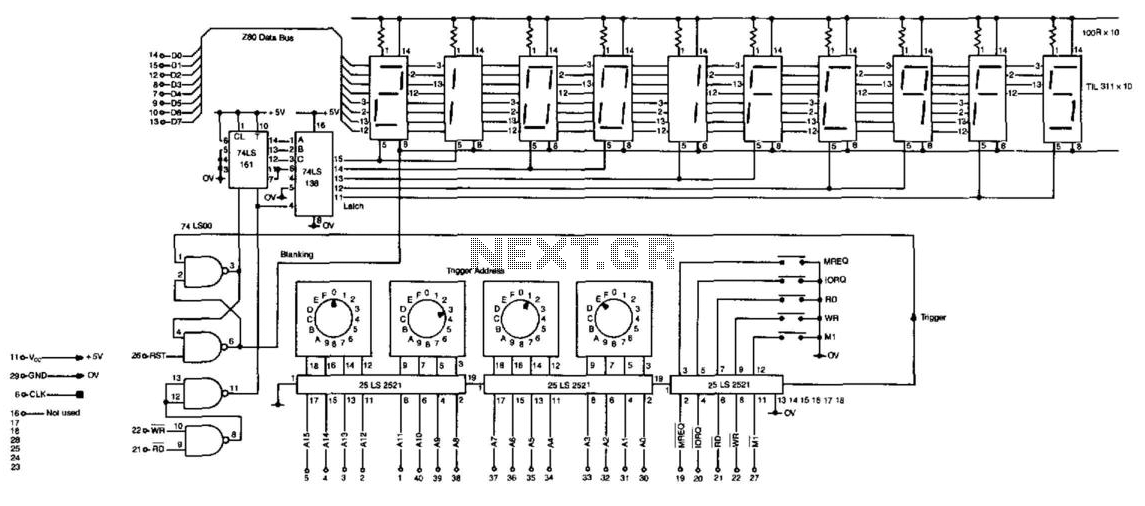
This simple circuit will trace the program execution and help point to the problems. Although the circuit shows connections for a Z-80, the circuit can very easily be adapted for any 8-bit microprocessor or with additional circuitry for CPUs of any bus width. The circuit consists of a 5-byte hexadecimal display and comparator, which are wired to a 40-pin IC test clip.
The test clip sits over the microprocessor (in this case a Z-80), where it gets power and all the required signals. The address bus and control lines are fed to the comparator, where (by means of switches) a trigger condition can be set.
Following the trigger, the next 5 occurrences of either RD or WR will latch the contents of the data bus into the 5 hex displays, each in turn. For example, select address 0000 Ml Rd and reset the CPU. The displays will show the very first instruction fetch, followed by its data and any consequent action.
Even details, such as stack writes and subroutine addresses, are included. To trace longer portions of a program the address switches can be incremented to follow the execution path. 🔗 External reference
Related Circuits
How the circuit works. The circuit comprises a non-inverting amplifier with a final output buffer stage or voltage follower for impedance matching. The described circuit functions as a non-inverting amplifier, which is designed to amplify an input voltage while maintaining...
Overcome a major drawback of the SPI bus. The I2C bus is a highly convenient design that requires only four wires to connect multiple chips. Each chip receives the same information but responds only to a specific address located...
The IEEE-1284 bus specifies a parallel printer bus with data transfer speeds exceeding 1 MBps. It defines a point-to-point asynchronous bi-directional interface. Devices can be either 1284 compatible (older parallel port devices) or 1284 compliant. The maximum recommended length...
This article was previously published, but the intention is to spread the idea further, potentially inspiring new concepts. An improved version was being developed using an ULN2803A instead of multiple BC547B transistors and optional Zener diodes to ensure that...
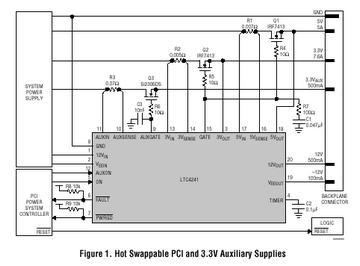
The LTC 4241 is a Hot Swap controller that enables safe insertion and removal of a board from a live PCI-bus slot. It features a primary controller that manages the four PCI supplies, along with an independent auxiliary controller...
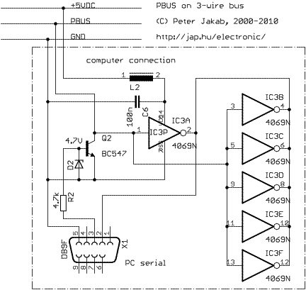
PBUS is an RS485-like multi-drop bus for interconnecting PIC and other microcontroller-driven devices. Protocol and software is written by Jap. Just include a separate pbus library file into your project and add your command handlers for the specific device...
Warning: include(partials/cookie-banner.php): Failed to open stream: Permission denied in /var/www/html/nextgr/view-circuit.php on line 713
Warning: include(): Failed opening 'partials/cookie-banner.php' for inclusion (include_path='.:/usr/share/php') in /var/www/html/nextgr/view-circuit.php on line 713