
Zero-point-switching-temperature-control
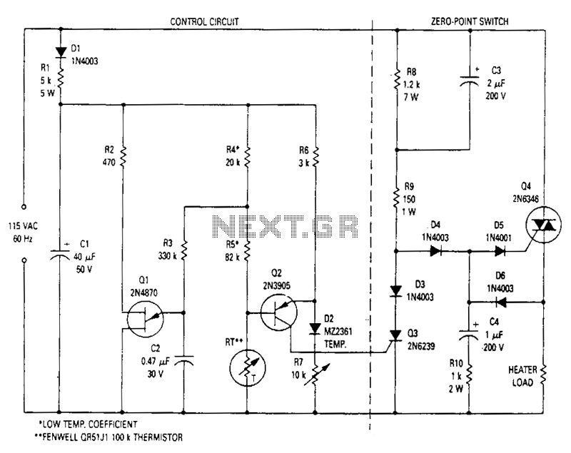
This modulated triac zero-point switching circuit controls heater loads operating from 115 Vac. Circuit operation is best described by splitting the circuit into two parts. The circuit on the right is the zero-point switch; to the left is the proportional control for the zero-point switch.
The modulated triac zero-point switching circuit is designed to effectively control heater loads that operate at 115 Vac. This circuit utilizes a triac, which is a semiconductor device that can control power to the load by switching it on and off at specific intervals. The operation of the circuit can be divided into two main sections: the zero-point switch and the proportional control mechanism.
The zero-point switch is responsible for turning the heater load on and off at the zero-crossing point of the AC waveform. This minimizes electrical noise and reduces stress on the triac, enhancing the longevity of the components. By activating the load at the zero-crossing point, the circuit ensures that the switching occurs when the voltage is at its lowest, which helps in reducing electromagnetic interference (EMI).
The proportional control section adjusts the duration for which the heater load remains on, based on the desired temperature or heating level. This is typically achieved through a feedback mechanism that monitors the temperature and adjusts the pulse width of the triac accordingly. As a result, the heater can maintain a stable temperature by varying the amount of power delivered.
In summary, the combination of the zero-point switching and proportional control allows for efficient and precise control of heater loads, providing a reliable solution for heating applications while minimizing energy consumption and potential electrical noise. This circuit design is particularly beneficial in environments where precise temperature control is essential.This modulated triac zero-point switching circuit controls heater loads operating from 115 Vac. Circuit operation is best described by splitting the circuit into two parts. The circuit at right is the zero-point switch; to the left is the proportional controHor the zero-point switch. 🔗 External reference