
Zero-power regulator circuit diagram
The zero-power regulator circuit operates effectively by leveraging the principles of zero-crossing detection and pulse counting, making it an ideal solution for applications requiring precise power control. The integration of components such as operational amplifiers and counters allows for a versatile design that can be adapted to various load requirements. The use of a triac for power control enables efficient handling of AC loads, providing a robust and reliable operation.
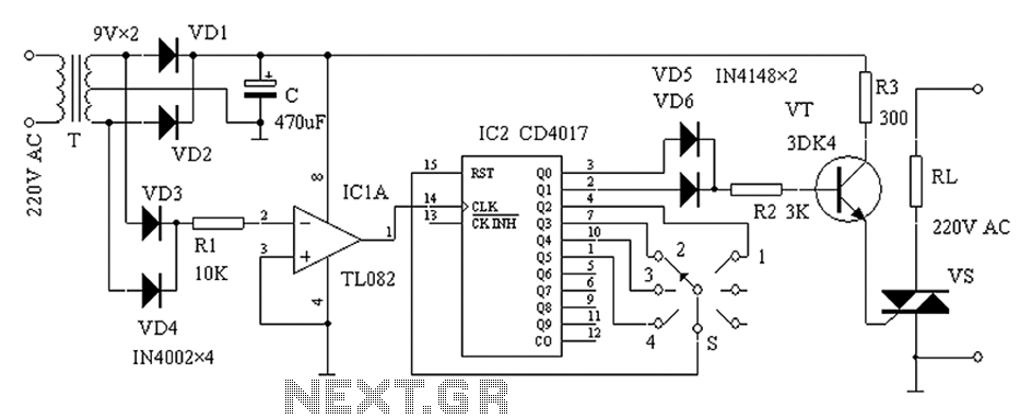
The circuit begins with the AC mains voltage being transformed down to a lower level by the transformer T, which is crucial for safely powering the subsequent components. The full-wave rectification performed by diodes VD1 and VD2 converts the AC voltage into pulsating DC, which is then smoothed by the capacitor C. This process ensures that the operational amplifier IC1 receives a stable voltage for accurate zero-crossing detection.
Operational amplifier IC1 is configured in an inverting manner, where it detects the zero points of the AC waveform. This detection is critical as it generates a pulse whenever the input voltage crosses zero, allowing IC2 to count these events. The CD4017 counter is particularly suited for this application as it can handle multiple outputs, facilitating the generation of various trigger signals based on the position of the power adjustment switch S.
The triac, in conjunction with the selected thyristor VS, provides a means to control the power delivered to the load. By adjusting switch S, the user can select different power levels, effectively modulating the output based on the operational requirements. This flexibility is essential for applications such as motor speed control or light dimming, where varying power levels are necessary.
The design's robustness is further enhanced by the careful selection of components rated for the expected load conditions, ensuring longevity and reliability in operation. Overall, this zero-power regulator circuit exemplifies an efficient and adaptable solution for power management in various electronic applications. As shown in the zero-power regulator circuit is simple, reliable and able to work. It is suitable for all kinds of electric power adjustment appliance, series wound motor power adjustment and the like. Circuit operation principle of the device as shown, it is from the power circuit, the AC zero-crossing detection circuit, decimal counter/pulse distributor and triac and other components. After the 220V mains power transformer T Buck, diode VD1, VD2 rectified full wave rectifier circuit constituted by the C filter is supplied after the whole circuit.
Via diode VD3, VD4 full-wave rectified, obtained after the pulsating DC voltage by R1 applied to the inverting input of the operational amplifier IC1 is. When the zero-ripple voltage (AC voltage is zero), IC1 then there have been zero pulse. IC2 pulse for counting and allocation of zero-crossing pulses to generate SCR trigger signal. S is the power adjustment switch to adjust the power AC load change IC2 counting by S. For example, when the S in the 3 file, IC2 carried quaternary counted every four zero-input pulse produces only two trigger pulse to trigger the triac turned on, so that the file for the half-power profile.
The figure shows a 4-speed, due to the IC2 with 10 outputs, the appropriate combination of these outputs, you can get different power profiles. VT connected as a high-current switch, different flows through the thyristor VS large current trigger, thus making it work reliably.
Wherein IC1 adopt a common operational amplifier integrated circuit (eg LM324N, TL082 etc.). IC2 use CD4O17. VT use 3DK4 or other medium power switching transistor can, 1OO. VS should be selected based on the current load, the pressure of not less than 600V, inductive load withstand voltage value can be increased. T uses 2 ~ 3W power transformer secondary electric pressure 9V. S selector switch for the power adjustment, optional ceramic band switch. No special requirements other components, according to the illustrated value selection.
Related Circuits
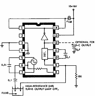
This electronic liquid detector circuit diagram utilizes the ULN2429A monolithic bipolar integrated circuit, which is designed to detect the presence or absence of various types of liquids. The detection mechanism involves comparing the resistance of a probe immersed in...
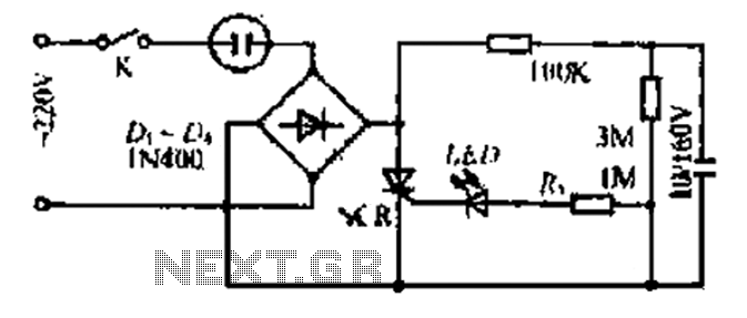
20V child-friendly power supply circuit for a foreign vine wine light, including a bulb and plug. The circuit features a bridge rectifier. The lamp access point is designed for a 10-100W bulb with a compact size. The output is...

All of ACC's repeater and remote base products support the control of synthesized remote base transceivers. One form of frequency control supported is compatible with transceivers using thumbwheel frequency selection. The controllers supply BCD (binary coded decimal) formatted data...
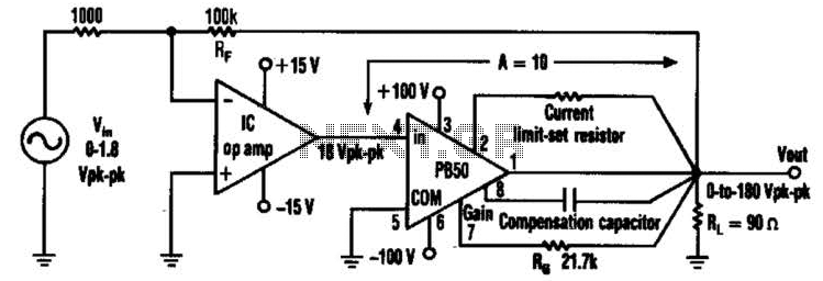
An Apex PB50 Booster Amplifier, along with an integrated circuit (IC) operational amplifier, can be utilized in a high-voltage operational amplifier configuration to convert a small analog signal into a 180-V peak-to-peak signal. Apex Microtechnology produces a variety of...

The ESR Meter is essentially an AC Ohmmeter equipped with specialized scales and protective circuitry. It provides continuous readings of series resistance in electrolytic capacitors. Operating at 100 kHz, it maintains the capacitive reactance factor close to zero. The...
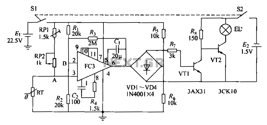
The circuit diagram illustrates an electronic thermometer. RT represents the thermistor, while A denotes an integrated operational amplifier. The diodes VD1 to VD4 provide a unidirectional output signal. The transistors VT1 and VT2 form a switching circuit. When the...
Warning: include(partials/cookie-banner.php): Failed to open stream: Permission denied in /var/www/html/nextgr/view-circuit.php on line 713
Warning: include(): Failed opening 'partials/cookie-banner.php' for inclusion (include_path='.:/usr/share/php') in /var/www/html/nextgr/view-circuit.php on line 713