
Zero sequence voltage phase protection circuit 2
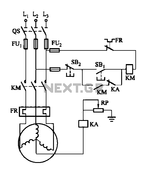
The circuit involves a potentiometer connected in series with the relay to allow for fine-tuning of the voltage supplied to the relay coil. This adjustment is critical for maintaining the proper operation of the motor, particularly in scenarios where the relay may fail to engage or disengage as intended. The potentiometer typically consists of three terminals: two connected to the power supply and one connected to the relay. By adjusting the wiper of the potentiometer, the voltage across the relay can be modified, ensuring that it receives the appropriate voltage level necessary for reliable operation.
In the schematic, the relay (KA) is represented as a switch that opens or closes based on the voltage applied to its coil. The motor is connected to the relay's output contacts, allowing it to be powered on or off depending on the relay's state. Proper sizing of the potentiometer is essential; it should be rated to handle the voltage and current levels in the circuit. Additionally, the circuit may include protective components such as diodes to prevent back EMF from damaging the relay during operation.
Overall, the integration of a potentiometer in this design allows for enhanced control over the relay's performance, ensuring that the motor operates reliably even in the presence of potential relay malfunctions.Drawing, potentiometer RP for adjusting the operating voltage of the relay KA, ensure that the motor work normally when E KA does not operate reliably action phase failure occu rs.
Related Circuits

A 555 timer (IC1) controls a 4017 CMOS decade counter. The first four outputs of the 4017 drive a CA3079 zero-voltage switch. Pin 9 of the CA3079 is utilized to inhibit output from pin 4, effectively disabling the stream...
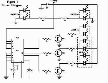
It consists of a 4047 low-power monostable/astable multivibrator, IC1, used in the astable mode to provide the timing pulses to control the flash rate of the LEDs. To accomplish the astable mode, pins 4, 5, 6, and 14 are...
All miniature electronic devices operate on batteries. Some require higher than standard battery voltages for efficient operation. When a battery of the required voltage is unavailable, additional cells must be connected in series to increase the DC voltage, which...
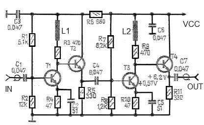
A simple and effective antenna amplifier can be built using the provided circuit diagram. This amplifier is designed for the frequency range of 35 kHz to 150 MHz. It utilizes transistors, offering a low non-linearity of 3 dB and...
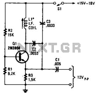
A simple oscillator for intermediate frequency (IF) alignment at 455 kHz can be useful in field testing or in scenarios where a standard signal generator is available. The inductor (L1) should resonate at the desired output frequency with the...

When the L and R signals are equal, no output is present from U1, and pin 6 is at a steady 4.5 V. Unbalanced audio causes the LEDs to vary in brightness, which indicates a difference that corresponds to...
Warning: include(partials/cookie-banner.php): Failed to open stream: Permission denied in /var/www/html/nextgr/view-circuit.php on line 713
Warning: include(): Failed opening 'partials/cookie-banner.php' for inclusion (include_path='.:/usr/share/php') in /var/www/html/nextgr/view-circuit.php on line 713