
Zero volt switching circuit diagrams
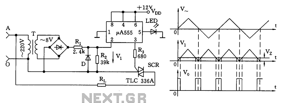
The zero volt switching circuit is designed to enhance the efficiency of AC voltage control by utilizing the principle of zero crossing detection. This method is pivotal in reducing electromagnetic interference (EMI) associated with switching operations in electronic circuits. The circuit employs a 555 timer configured as a comparator, which detects the zero crossing point of the AC waveform. By setting the static bias voltage at terminal 5 to a specific range (0.7V to 1V), the circuit establishes a reference voltage that is crucial for triggering the SCR (Silicon Controlled Rectifier) at the precise moment when the AC voltage crosses zero.
In practice, the circuit's operation begins with the AC voltage waveform approaching zero volts. As the waveform crosses this threshold, the 555 timer outputs a pulse that triggers the SCR, allowing current to flow and power to be delivered to the load. This switching action occurs at the zero crossing point, which is beneficial for reducing the generation of electrical noise and minimizing the stress on the connected components. The SCR remains in the conducting state until the current through it falls below a certain threshold, at which point it turns off, effectively stopping the flow of AC voltage to the load.
The waveform diagram referenced in the description illustrates the relationship between the AC voltage, the trigger pulse generated by the 555 timer, and the resultant SCR switching action. The use of a triangle wave in the diagram serves to simplify the visualization of the zero crossing detection process, facilitating a clearer understanding of the timing relationships involved. This method of operation is particularly advantageous in applications where minimizing EMI is critical, such as in sensitive electronic devices and communication equipment.
Overall, the zero volt switching circuit represents a practical solution for effective AC voltage control while maintaining compliance with electromagnetic compatibility standards, thus ensuring reliable operation in various electronic applications. As shown, the zero volt switching circuit in the zero crossing of the AC voltage generated trigger pulse. In order to trigger the zero crossing of the 555 limit comparator conn ected into a single form, the comparison voltage point by setting the corresponding static bias voltage control terminal 5 feet 0.7 ~ 1V, as a comparison with a LED device. It can be used as a reference voltage indicating the presence of a light-emitting. Working Process waveform diagram shown in Figure (b) below. Here, in order to illustrate the problem, it will be drawn into a triangle wave sine wave, but does not affect the analysis process.
Since the reference voltage is relatively low, therefore, the trigger level near zero volts to produce a pulse width narrower. Thus, SCR zero crossing of the AC mains voltage switched on and off, can weaken the impact of high-frequency radiation interference and adjacent appliances.
Related Circuits
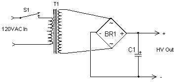
The circuit can produce about 250-500mA at 2KV, depending on the transformer. For C1, you can use the capacitor out of an old microwave. This circuit is mainly provided as a demonstration of using commonly available parts for something...
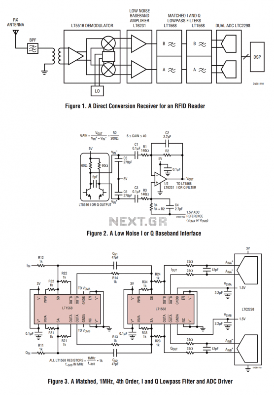
Figure 1 shows the block diagram of a direct conversion RF receiver—the receiver demodulates an RF carrier directly into a baseband signal without an intermediate frequency down-conversion (a zero IF receiver). The antenna, shared by both the transmitter and...
The frequency range for the FM transmission band is 90 MHz (megahertz, or 90 million cycles per second). Due to the variable tuned circuit in the FM transmitter, it can be tuned to a specific frequency within the local...
The voltage regulator integrated into the Arduino Uno is a linear-type regulator, which exhibits poor efficiency. When operating the ATmega238 at 5V with a 9V battery, nearly half of the battery's energy is wasted as heat by the regulator....
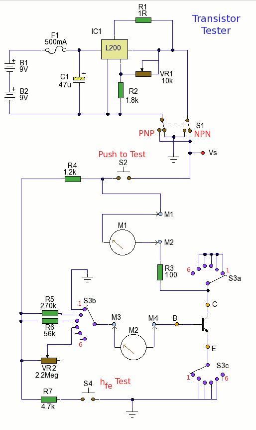
Using the tester is straightforward. Begin with the power off and insert a transistor into the test socket. Set switch S1 for either NPN or PNP configuration and rotate switch S3 to the desired test position. Adjust variable resistor...
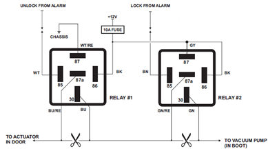
The circuit diagram displayed below illustrates a single-wire vacuum control system for pneumatic locking, commonly utilized in vehicles from Jaguar, Audi, and Mercedes. The circuit operates by managing the vacuum pressure required to engage or disengage the pneumatic locking mechanism....
Warning: include(partials/cookie-banner.php): Failed to open stream: Permission denied in /var/www/html/nextgr/view-circuit.php on line 713
Warning: include(): Failed opening 'partials/cookie-banner.php' for inclusion (include_path='.:/usr/share/php') in /var/www/html/nextgr/view-circuit.php on line 713