
Using the power switch integrated circuit level one controlled circuit sink type

The described circuit utilizes an integrated circuit (IC) designed for liquid level sensing and control. The primary function of this circuit is to maintain the water level within a specified range by activating and deactivating a pump based on the readings from two electrodes, A and B.
Electrode B serves as the lower threshold sensor. When the water level falls below 2 feet, it generates a low voltage signal (0V), which triggers the integrated circuit A to engage. If the water level drops further to 4 feet, the circuit activates relays KA and KM. These relays are responsible for controlling the pump's operation. Once activated, the pump begins to fill the water tank until the water level rises above the upper threshold set by electrode A.
Electrode A functions as the upper threshold sensor. When the water level reaches this electrode, exceeding 2 feet and registering a voltage of 1.5V, the integrated circuit detects this condition and deactivates the relays KA and KM. This action stops the pump, preventing overfilling of the water tank.
The reliability of this circuit is enhanced by its simple design and high sensitivity, making it suitable for various applications in water level management systems. The integration of relays allows for effective control of the pump, ensuring that the water level remains within desired parameters without manual intervention. Overall, this automatic liquid level control circuit is an efficient solution for maintaining optimal water levels in tanks and reservoirs.As a result of the power switch integrated circuit A, it has a simple circuit, the sensitivity is high, working and reliable. It belongs to the people filling liquid level auto matic control circuits. When the water level in the following electrode B, A 2 feet low (ov), A is turned on, 4 feet low (Ov), pull the relay KA, KM pull, pump up and running, the water tank water; when the water level rose to electrodes a, a 2 feet high ( 1.5V), a cutoff, KA and KM release, the pump stops irrigation.
Related Circuits
A simple FM transmitter connects a home entertainment system to a portable radio that can be moved around the house and into the backyard. For instance, music can be played from a CD player in the living room and...
The 15V zener is fed via the 4.7k resistor from the input. With 0.6V across the base-emitter of the PNP transistor, this establishes a voltage of 14.4V across the 3.3k resistor, so there must be a current of nearly...
This circuit is a simple form of the commercial UPS, the circuit provides a constant regulated 5 Volt output and an unregulated 12 Volt supply. In the event of electrical supply line failure the battery takes over, with no...
The LMD18200 is a 3A H-Bridge designed for motion control applications. The device is built using a multi-technology process that combines bipolar and CMOS control circuitry with DMOS power devices on the same monolithic structure. It is ideal for...
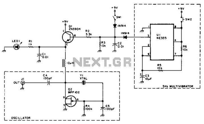
A useful marker oscillator can be constructed using an NE555 timer to generate pulses at an audio frequency. This design facilitates the detection of the signal even amidst interference. The crystal frequency can range from 1 to 30 MHz. The...
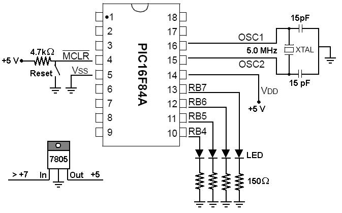
To start working with microcontrollers, several essential items are required. The PICSTART Plus kit, part number DV003001, was purchased from Microchip. This kit contains a sample PIC16F84 microcontroller chip, which in this case is a PIC16F84A chip. This chip...