
TDA4866 test circuit diagram

The TDA4866 test circuit is designed to evaluate the performance of the TDA4866 integrated circuit, which is commonly used in vertical deflection applications in television and display systems. The circuit's operation is initiated by the application of a positive supply voltage (VP), which powers the internal components and facilitates the generation of the necessary waveforms for vertical deflection.
The feedback voltage (VFB) is critical for maintaining the stability and accuracy of the output waveform. In this configuration, the circuit is capable of handling a feedback voltage of 40V, with a maximum allowable voltage of 60V, ensuring that the circuit operates within safe limits under various load conditions. The reference resistor (Rref) plays a pivotal role in determining the feedback loop gain, which influences the overall performance of the circuit.
The differential input stage is designed to receive input signals that represent the desired vertical deflection. The inverting input terminal processes these signals, allowing for the generation of a vertical sawtooth waveform. This waveform is essential for driving the vertical deflection coils in a display system, providing the necessary movement of the electron beam or image pixels.
The output stage amplifies the sawtooth voltage, ensuring that it reaches the appropriate levels required for effective deflection. The use of a dummy load resistance simulates the behavior of a deflection coil, allowing for accurate testing and evaluation of the circuit's performance under realistic conditions.
Capacitors and resistors are selected based on the desired frequency response and stability of the circuit. The feedback capacitor (CFB) of 22 microfarads is chosen to filter out high-frequency noise, while the capacitor (CSP) can vary between 10 and 330 nanofarads, allowing for tuning of the circuit's response. The series resistor (RSP), ranging from 10 to 22 ohms, is used to limit current and protect the circuit from potential overload conditions.
Overall, the TDA4866 test circuit is a comprehensive setup for evaluating the functionality and performance of the TDA4866 integrated circuit in vertical deflection applications, providing essential insights into its operation and characteristics. As shown for the TDA4866 test circuit. When the positive supply voltage VP, supply voltage VFB plus flyback circuit operates when the input signal changes from 1 foot and 2 fee t inside the differential input stage input to the inverting input terminal and inverting input terminal, vertical sawtooth voltage output stage to enlarge after the output of 6 feet and 4 feet. The test circuit used as a dummy load resistance 6 alternative deflection coil, while the output signal is fed back through Rref 9 feet.
40V VFB 60V, RFB 100, CFB 22 F, CSP 10 ~ 330nF, RSP 10 ~ 22 .
Related Circuits
This circuit is a simple analog multiplier. The operation of the circuit can be understood by considering A2 as a controlled gain amplifier that amplifies V2, with its gain dependent on the ratio of the resistance of PC2 to...
Measurements were conducted using a modified program to measure the voltage applied at the drive electrode and the voltage at the sense electrode. Conductance was calculated using the formula 0.01S * V_resist / (V_applied * V_resist). The initial version...
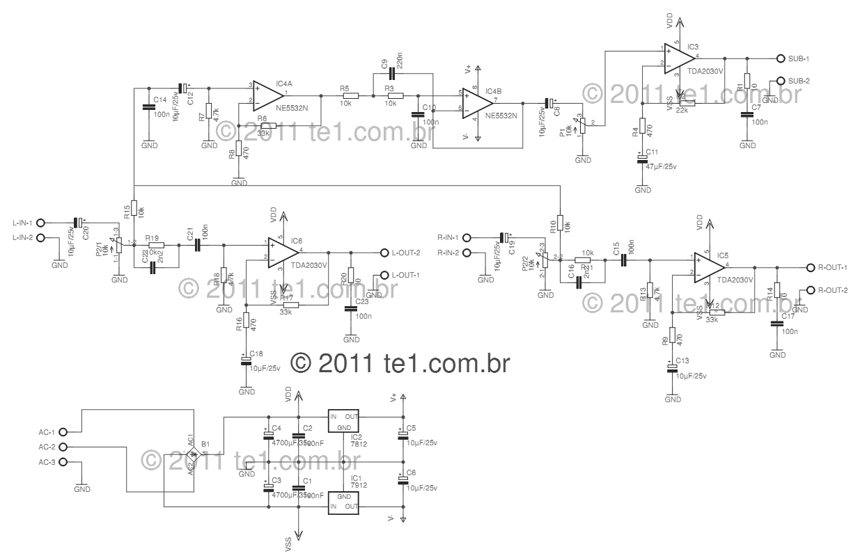
This circuit is a complete application for a 2.1 amplifier system, featuring two satellite speakers for TDA and one subwoofer. It is commonly used in commercial applications to enhance the audio output of computers using a stereo amplifier along...
This small transistor tester employs a simple visual indication system to perform a quick go/no-go check on both NPN and PNP transistors. When testing a functioning NPN transistor, the green LED (D1) will flash, while the red LED will...
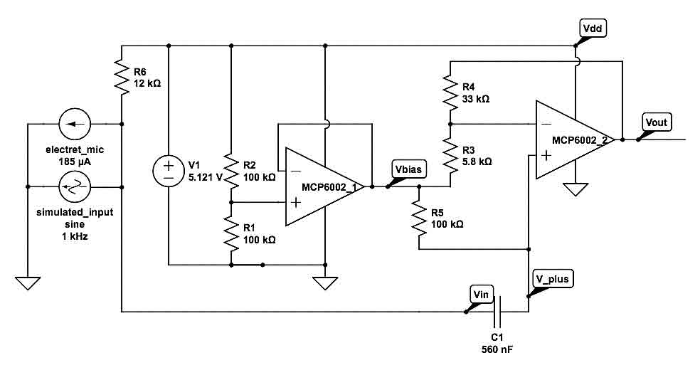
This is a simple microphone preamplifier circuit which you can use between your dynamic microphone and any equipment designed to work with an electret microphone (2 wire connection to electret capsule). This amplifier amplifies the low level signal to...
Fog Lamp Switch Circuit. In many countries, it is now mandatory or at least recommended to have a rear fog light on a trailer, with the additional requirement that when the trailer is coupled to the car, the rear...