
DC relay delayed release circuit 2 b

The relay circuit in question utilizes a coil that, when energized, activates the relay mechanism. Connecting a resistor (Rf) or a diode (VD) in parallel with the coil serves to modify the electrical characteristics of the circuit during the deactivation phase. When the relay coil is energized, it generates a magnetic field that closes the relay contacts. However, upon deactivation, the collapsing magnetic field can induce a voltage spike due to the coil's inductance, which may cause damage to other components in the circuit.
In the configuration with the resistor Rf, the resistor provides a path for the current to dissipate gradually when the relay is turned off. This gradual dissipation helps to mitigate the effects of the induced voltage spike, allowing for a more controlled release of the relay contacts. The presence of the resistor results in a longer time constant for the current decay, which can be beneficial in applications where a delayed release is desired.
In contrast, when the circuit depicted in Figure 6-24 (b) does not include the resistor Rf, the relay coil will experience a more abrupt reduction in current. This can lead to a faster release of the relay contacts but may also result in higher voltage spikes, potentially affecting the reliability and longevity of the circuit components.
Overall, the choice between using a resistor or a diode in parallel with the relay coil depends on the specific requirements of the application, such as the need for a delayed release versus the potential risk of voltage spikes. Proper selection and implementation of these components are crucial for ensuring the effective operation of relay circuits in various electronic systems. Circuit shown in Figure 6-24. Both ends of the relay coil in parallel with a resistor Rf or auxiliary diode VD, is equivalent to power after a short circuit coil core increase, thus making prolonged release. Figure 6-24 (b) of Rf can not.
Related Circuits
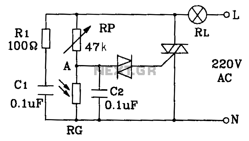
This circuit diagram illustrates an automatic lighting system designed for use in hospitals, dormitories, corridors, and public spaces. The system utilizes a photosensitive resistor to control the lighting, ensuring that lights are automatically turned off during the day and...
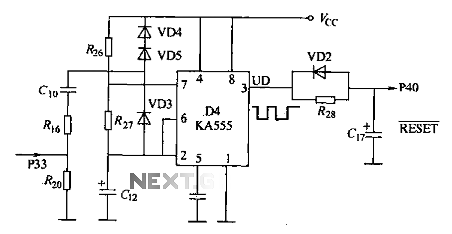
Anti-jamming circuit (watchdog circuit): KA555 interference when analog baseband circuit is shown in Figure 18-14. The KA555 is a hybrid analog/digital integrated circuit. The input signal is connected to specific pins, while the power supply is 5V and the...
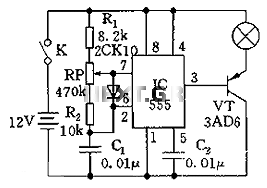
The circuit illustrated in the figure is a dimmer using the 555 timer as the core component. The 555 timer, along with resistors R1, RP, R2, and capacitor C1, forms an astable multivibrator. The oscillation frequency, f, is calculated...
This is a simple function generator built around a single 8038 waveform generator IC. The circuit is capable of producing sine, square, or triangle waves within a frequency range of 20Hz to 200kHz. The function generator circuit utilizes the 8038...
This audio processor circuit features the SSM2045 integrated circuit (IC), designed specifically for electronic music applications, along with the 741 operational amplifier (op-amp) IC. The circuit is configured as a low-pass filter with a DC voltage control for gain....
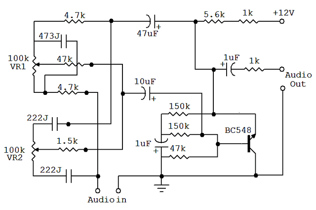
An audio equalizer circuit is utilized to modify the frequency response of an audio signal. This particular equalizer circuit is designed for adjusting the bass and treble (tone) levels of an audio amplifier. To integrate this equalizer circuit with...