
0.7 - 24V /2A Power Supply

The Variable DC Power Supply circuit is designed to provide a versatile and adjustable power source for various electronic projects. The circuit typically includes a transformer, rectifier, filter capacitor, voltage regulator, and control potentiometers.
The transformer steps down the AC voltage from the mains supply to a lower AC voltage suitable for the intended output. The rectifier, usually a bridge rectifier configuration, converts the AC voltage to pulsating DC. Following this, a filter capacitor smooths the pulsating DC to provide a more stable voltage output.
The voltage regulation is achieved using a linear voltage regulator, which can be adjusted to output a variable voltage up to 24V. This regulator is crucial for maintaining a consistent voltage level despite variations in load or input voltage.
Potentiometer P1 is used to set the maximum output current limit, providing protection against overcurrent conditions that could damage connected components. This feature is particularly useful in experimental setups where the load may not be well-defined.
Potentiometer P2 adjusts the output voltage. It is recommended to use a logarithmic taper type for P2, as this allows for a more linear response in voltage adjustment, making it easier to set precise voltage levels.
Overall, the design of the Variable DC Power Supply emphasizes reliability and adaptability, making it an essential tool for hobbyists and professionals alike. The circuit can be modified to suit specific needs, whether by changing component values or adding additional features such as digital displays or remote control capabilities.A Variable DC Power Supply is one of the most useful tools on the electronics hobbyist`s workbench. This circuit is not an absolute novelty, but it is simple, reliable, "rugged" and short-proof, featuring variable voltage up to 24V and variable current limiting up to 2A. Well suited to supply the circuits shown in this website. You can adapt it to your own requirements as explained in the notes below. # P1 sets the maximum output current you want to be delivered by the power supply at a given output voltage. # P2 sets the output voltage and must be a logarithmic taper type, in order to obtain a more linear scale voltage indication.
# You can choose t 🔗 External reference
Related Circuits
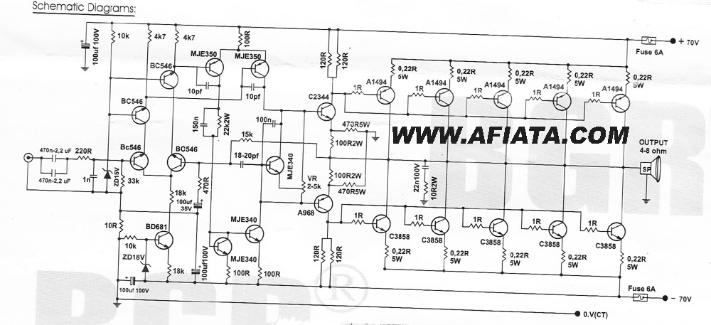
How many speakers can be attached to this amplifier, and what are the impedance and wattage values of these speakers? Please respond to my email. Sir, you made this amplifier, and it works properly for a lifetime. Which transformer...
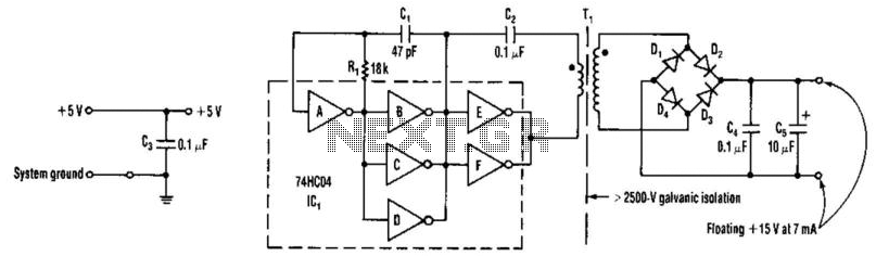
A DC-DC converter utilizes a 74HC04 to drive transformer Tl. Tl is a ferrite-core transformer from Fair-Rite, Inc., with part number 597-5000201, featuring a 7-turn primary winding and a 25-turn secondary winding. Kynar #30 wire wrap wire is employed...
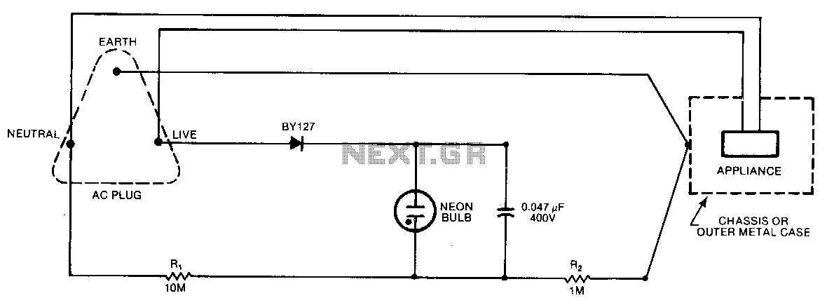
A continuous glow signifies that everything is normal; a blinking or extinguished neon bulb indicates a broken earth or ground connection, or interchanged neutral and live wires. In electronic circuits, a neon bulb is often used as an indicator light...
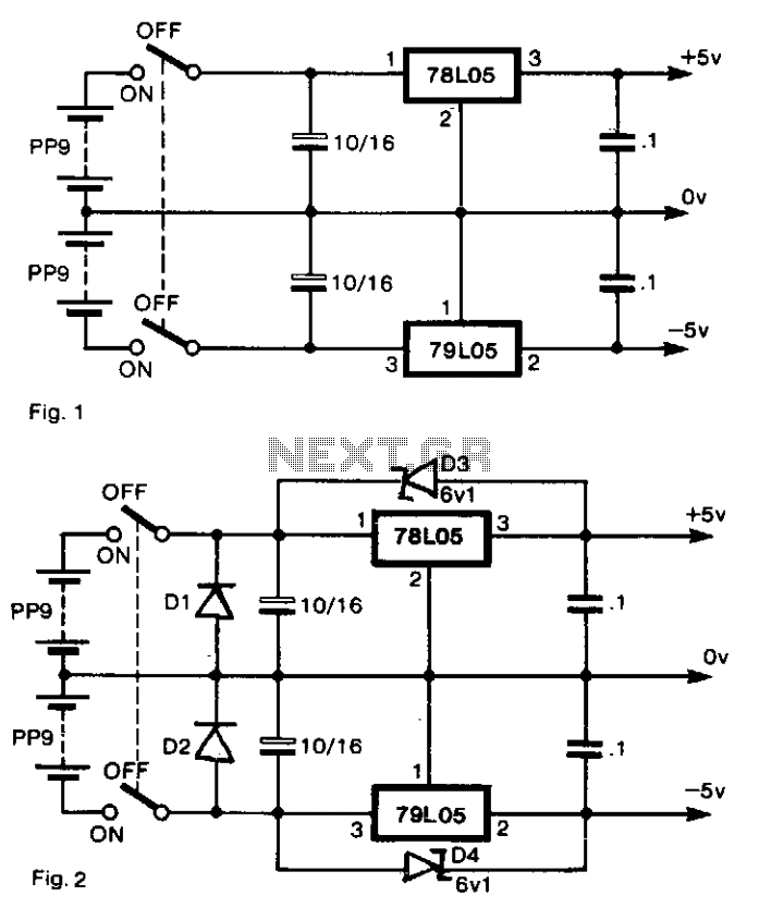
To generate regulated ±5-V supplies from a pair of dry batteries, the circuit shown in Fig. 1 is commonly utilized. To protect against inadvertent reverse connection of a battery, a diode in series with each battery would create an...
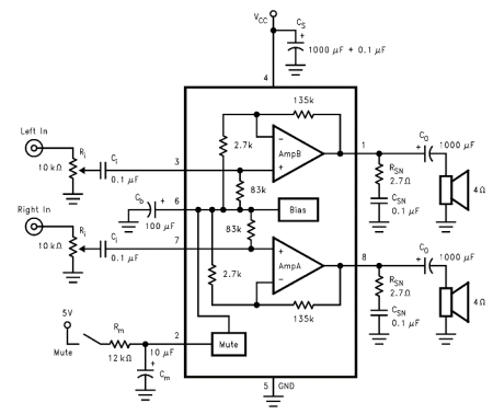
The internal mute circuit and pre-set gain resistors provide a cost-effective design solution. Output power specifications at both 20V and 24V supplies, along with a low external component count, offer significant value to consumer electronic manufacturers for stereo TV...
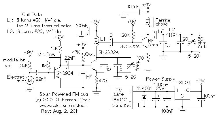
Numerous miniature FM transmitter bug circuits are available online; however, this particular design is distinctive as it operates entirely on solar power, eliminating the need for a battery. The transmitter will function as long as sunlight is incident on...