
1.3 Volt Power Source

The described circuit serves as a versatile power source, specifically designed to replace 1.3V mercury cells or similar small batteries. It is particularly beneficial in applications where low voltage is required, such as powering digital thermometers or multi-adapter front panels in computer systems. The circuit harnesses power directly from a PC, utilizing its existing power supply outputs.
The power connectors are color-coded for ease of identification: the red and black wires deliver a 12V supply, while the black and yellow wires provide a 5V supply. This dual supply configuration allows the circuit to be adaptable to various devices that may require different operating voltages. However, caution is critical when working with these high current outputs, as the risk of short circuits is significant. To mitigate this risk, it is advisable to incorporate an inline fuse rated at 100mA, which will protect the circuit from potential damage due to overcurrent conditions.
The circuit derives the necessary 1.3V from a red LED. When the LED is forward-biased, it exhibits a typical voltage drop of approximately 1.9V across its anode and cathode. This voltage is higher than what is suitable for devices designed for mercury cell operation. To reduce the voltage to a more appropriate level, a 1N4148 signal diode is placed in series with the LED. The diode introduces a voltage drop of about 0.6V, effectively lowering the output voltage to approximately 1.3V, which is suitable for the intended applications.
This circuit design exemplifies an efficient method of utilizing readily available components to create a reliable power source for low-voltage devices, ensuring compatibility and functionality in modern electronic applications.This is a replacement power source for 1.3V mercury cells or other small batteries. It has many uses and I use this circuit in my computer to power a front panel multi adapter which has a digital thermometer. This circuit takes it power from a PC. The power connectors have colour coded wiring, red and black are a 12V supply, black and yellow are a 5V supply.
These are extremely high current so absolute care must be taken to avoid short circuits and an inline fuse of 100mA is recommended. The 1.3V is derived from a Red LED. When on and forward biased the LED`s voltage drop between anode and cathode is about 1.9V, this is too high for mercury cell powered equipment, but fed in series with a 1N4148 signal diode drops around 0.6V, the su 🔗 External reference
Related Circuits
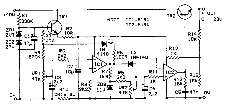
A variable power supply is required for repairs on CB and audio equipment, featuring excellent current limiting and protection. The designed circuit delivers a current from zero to approximately 4.25A at a voltage range of zero to about 23V....
National Semiconductor has been designing and manufacturing integrated circuits (ICs) for switch-mode power supplies for many years. The application of these devices is typically straightforward, supported by comprehensive documentation. A common example of a switch-mode power supply is based...
To obtain the power supply graphs on the previous page, the circuit is designed to independently monitor the power sources with the addition of a few resistors. Diode D3 allows the solar panel voltage to charge the batteries, while...
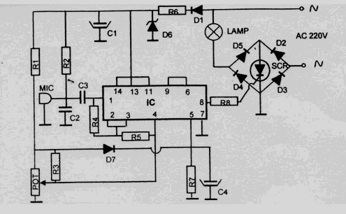
This disco lamp circuit is not a voice-operated switch (VOX) because it cannot differentiate between musical sounds and human voices. Instead, it is sound-activated. An interesting application of this circuit is to control disco lighting automatically using the musical...
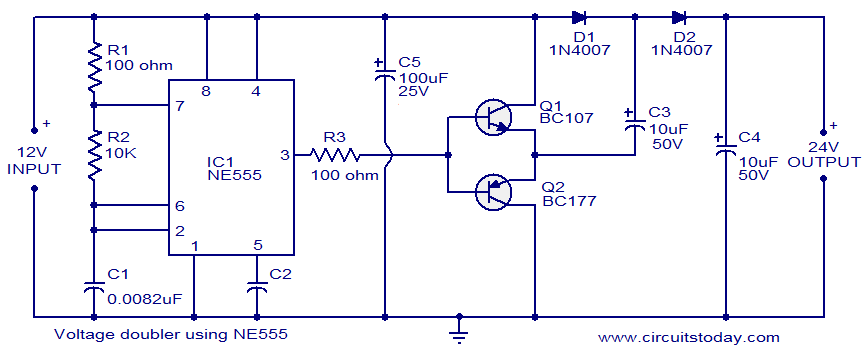
The circuit diagram of a simple voltage doubler using the NE555 timer is presented. In this configuration, the NE555 IC operates as an astable multivibrator at approximately 9 kHz. The bases of two transistors, Q1 and Q2, are connected...
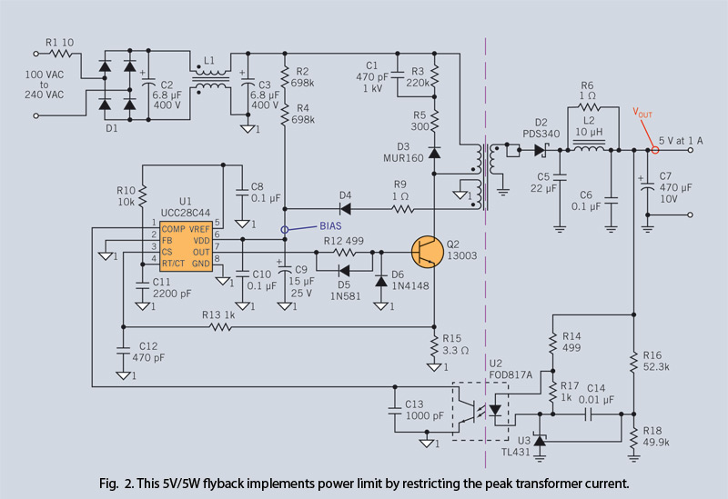
Through simple circuit modifications, designers can use peak current limiting to produce a constant current source. A constant current source is an essential component in various electronic applications, providing a steady output current regardless of load fluctuations or variations in...