
10 band graphic equalizer schematic

The circuit design features ten filter units, each tailored to operate within specific frequency bands dictated by the capacitance values of their capacitors. This configuration allows for precise tuning of audio signals across a range of frequencies, enhancing the overall sound quality. The use of potentiometers enables users to fine-tune the frequency response, allowing for customization based on individual preferences or specific audio requirements.
In stereo applications, the circuit is split into two identical sections, ensuring that both channels maintain a consistent frequency response. This design consideration is crucial for achieving a balanced audio output, preventing discrepancies that could arise from variations in component values or characteristics between the two channels.
The inclusion of switch S1 adds versatility to the circuit. When engaged, it isolates the equalizer circuit from the audio path, allowing for a direct signal flow that maintains a flat frequency response. This feature is particularly useful when the equalization is not desired, ensuring that the audio output remains unaltered during playback.
The overall circuit is designed to be integrated between a preamplifier and a final power amplifier. This positioning is strategic, as it allows the equalization process to occur before amplification, ensuring that the audio signal is optimally shaped before being sent to the power amplifier for driving speakers. Properly implementing this circuit can significantly enhance audio performance, providing users with the flexibility to tailor their listening experience.As shown in the diagram, there are 10 same units that only differ in capacitance values of capacitors which determine the frequency band of each filter. The potentiometers adjust the predetermined regions of frequency in each unit. If it is intended for stereo use then it will be supposed it is made in two pieces with as much as possible suited th
e materials, between the channels, so that do not exist differences in the regulation of each band frequencies. Switch S1 isolates the circuit EQ, when him we did not need and it ensures level [ flat ] response in the exit of circuit.
The circuit should be connected between preamplifier and in a final power amplifier. 🔗 External reference
Related Circuits
This circuit is designed to signal the exceeding of a fixed threshold in room noise through a flashing LED. Three fixed levels are selectable: 50, 70, and 85 dB. Two operational amplifiers provide the necessary gain for sounds captured...
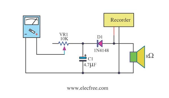
Expensive stereo systems generally feature VU meters that help indicate maximum power levels to prevent overloading. However, typical radio tape players do not include VU meters. A potential solution involves using a multimeter as a replacement. This can be...
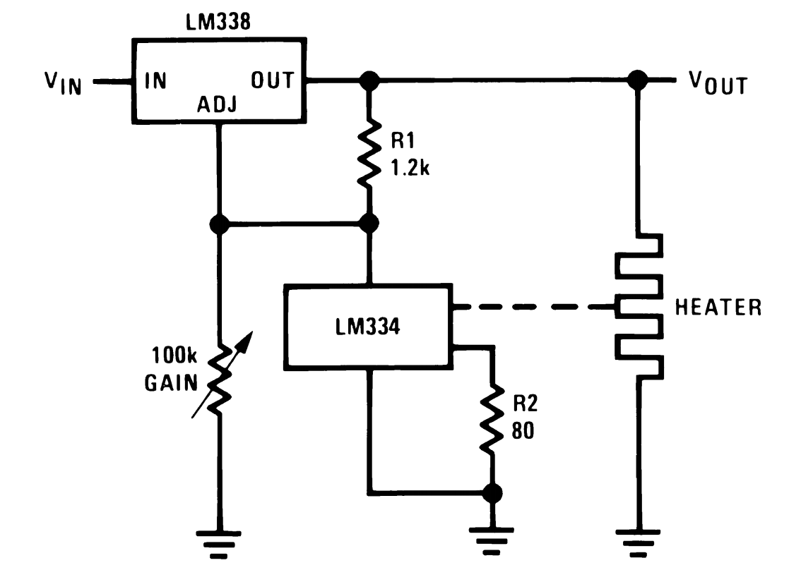
This power supply utilizes a single 7812 IC voltage regulator along with multiple external pass transistors, enabling it to deliver output load currents of up to 30 amps. The circuit design incorporates a 7812 linear voltage regulator, which is...
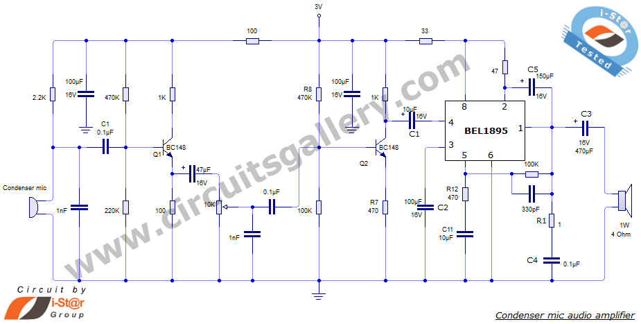
This document presents an audio amplifier circuit suitable for use in walkie-talkies, low-power transmitters, and packet radio receivers. The circuit utilizes a condenser microphone audio amplifier that delivers high-quality audio output of 0.5 watts at 3 volts. The design...
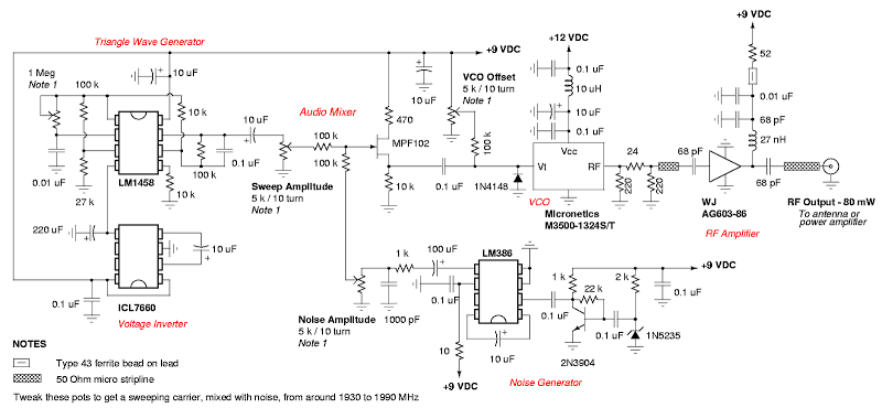
A DIY GSM jammer schematic diagram designed for use exclusively with GSM1900, operating within the frequency range of 1930 MHz to 1990 MHz. The GSM1900 cellular network is utilized in the USA, Canada, and most countries in South America....
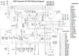
The electrical system of the 2005 Yamaha DT125X typically includes a CDI unit, battery, thermo unit, rectifier/regulator, servomotor, fuse, neutral switch, ignition coil, and main switch. The electrical schematic for the 2005 Yamaha DT125X outlines the interconnections and functionalities...