
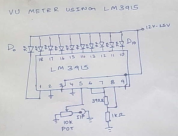
10 LED VU meter with LM3915

The circuit described operates with a supply voltage of 12 V, drawing a standby current of 10 mA, which can increase to a maximum of 80 mA during active operation. It is designed to accept an input voltage with a minimum of 20 mV RMS and has an indication range of 30 dB. The circuit utilizes an LED output with a current of 7 mA, driven by the reference voltage of 5 V provided by IC2, which is an LM3915 LED bar graph driver.
The resistive components include a trimmer potentiometer (R1) rated at 100 kΩ, which allows for fine-tuning of the circuit's gain or other parameters, alongside fixed resistors R2 (2.2 kΩ), R3 (1 MΩ), R4 (2.7 kΩ), and R5 (6.8 kΩ). These resistors are strategically placed to set the gain and biasing conditions for the operational amplifier IC1 (LM386), which is configured to amplify the input signal.
Capacitors in the circuit include C1 (0.47 µF), C2 (10 µF), C3 (47 nF), C4 (4.7 µF), C5 (0.1 µF), C6 (100 µF), and C7 (100 nF). These capacitors serve various functions, such as filtering, coupling, and decoupling, to ensure stable operation and prevent oscillations in the circuit. For instance, C2 may be used for power supply decoupling, while C1 could be part of an input coupling arrangement to block DC offsets.
Diode D1 (1N4148) is included in the design, likely for protection against reverse polarity or signal clamping, while D2 to D11 represent a series of LEDs or a bargraph display driven by the output of the LM3915. This visual indication allows for real-time monitoring of the input signal level, providing a clear visual representation of the amplitude of the incoming signal.
Overall, the schematic integrates these components to create a versatile amplifier and indicator circuit suitable for various audio and signal processing applications. The careful selection of components ensures that the circuit operates efficiently within its specified parameters.Supply voltage: 12 V. Supply current: 10 mA in stand-by, max. 80 mA. Input voltage: min. 20 mV rms. Indication range: 30 dB. LED currents: 7 mA. Ref. voltage of IC2: 5 V R1 - trimmer 100 k mini R2 - 2,2 k R3 - 1 M R4 - 2,7 k R5 - 6,8 k C1 - 0,47 uF C2 - 10 uF C3 - 47 nF C4 - 4,7 uF C5 - 0,1 uF C6 - 100 uF C7 - 100 nF IC1 - LM386 IC2 - LM3915 D1 - 1N4148 D2-D11 - bargraph or LED's 🔗 External reference
Related Circuits

The 10k resistors in question are R15, R17, R18, and R19 (R16 is located elsewhere). Their purpose is to isolate the input channels; otherwise, turning the volume control for one channel down to zero would also connect the output...
This is Version 1 of the VU meter that has been planned for construction. The final version will differ from the current one as its performance did not meet the requirements. This version cost approximately 100. The IC LM3915...
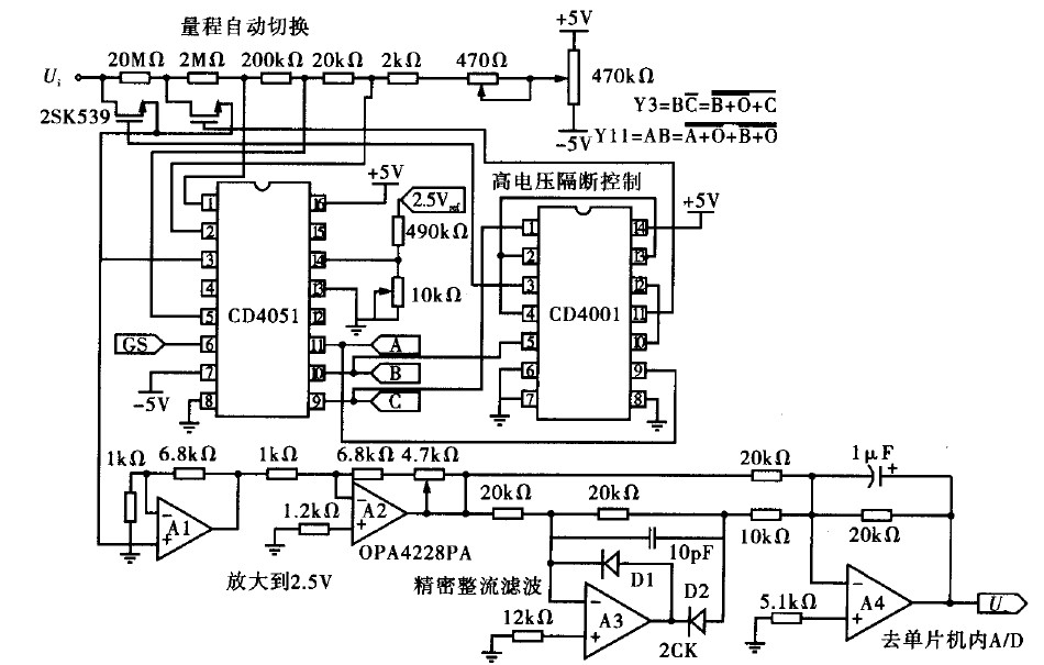
Voltage measurement is a fundamental aspect of electronic technology today, with increasing demands for accuracy and functionality in instruments. This is particularly critical when measuring signals with significant phase differences, as it is essential to ensure the accuracy of...
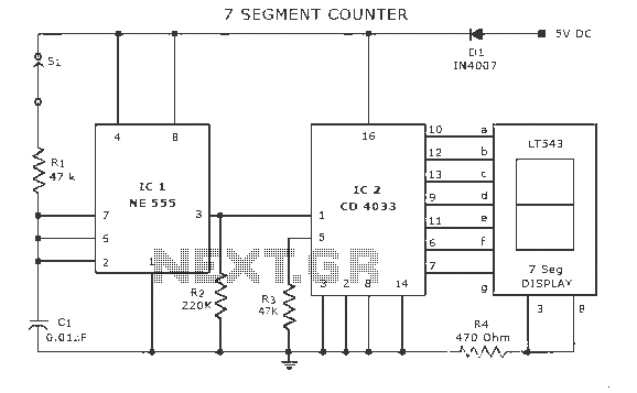
A display counter circuit is illustrated through a diagram featuring a seven-segment display controlled by the counter IC CD4033. This counter circuit is designed to visually represent incremental counts, enhancing its appeal for integration into various applications. An astable...

Most analog multimeters can measure resistance across a wide range of values; however, they can be inconvenient due to their reverse reading scale, which is also non-linear. This can lead to poor accuracy, especially at the high-value end of...
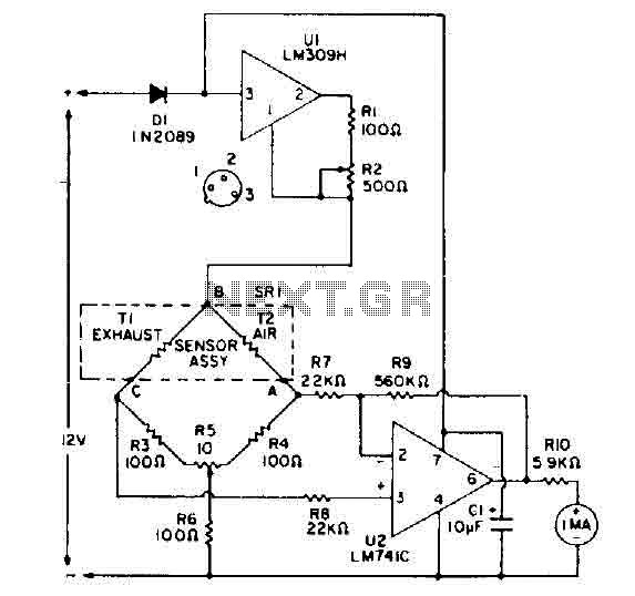
The bridge circuit consists of two resistors (R3 and R4) of 100 ohms each, and two thermistors (T1 and T2). At room temperature, the resistance of both T1 and T2 is approximately 2000 ohms. When exposed to a temperature...