
10W Audio Amplifier with Bass-boost

The audio amplifier design leverages the NE5532 dual operational amplifier, which is renowned for its high performance in audio applications. The circuit is configured to operate within a supply voltage range of ±18V, ensuring that the output power remains within the specified limits of 9.5 to 11.5 Watts. This power output is suitable for driving small loudspeaker cabinets, which are commonly used in various audio applications.
To enhance the low-frequency response, a bass-boost control is integrated into the feedback loop. This feature allows users to compensate for the natural roll-off of bass frequencies that occurs in smaller speaker systems. The bass boost can provide a significant enhancement of up to +16.4 dB at 50 Hz, making it possible to achieve a fuller sound profile without introducing distortion or compromising audio quality.
The frequency response characteristics of the amplifier are designed to ensure clarity across the audio spectrum. When the bass control is set to its lowest position, the amplifier still maintains a gentle rising frequency response. This includes an increase of +0.8 dB at 400 Hz, +4.7 dB at 100 Hz, and +6 dB at 50 Hz, all referenced to 1 kHz. This response curve indicates that even without bass enhancement, the amplifier is capable of delivering a balanced audio output.
Grounding is a critical aspect of the circuit design, as improper grounding can lead to unwanted hum and ground loops. To mitigate these issues, it is recommended that all ground connections for components such as J1, P1, C2, C3, and C4 be tied to a single grounding point. Additionally, C9 should be connected to the output ground to maintain signal integrity and minimize noise interference.
Overall, this audio amplifier design provides a practical solution for users seeking an effective and high-quality amplifier that can be easily assembled using readily available components. The incorporation of bass-boost functionality and careful attention to grounding enhances the performance and usability of the amplifier in various audio applications.This design is based on the 18 Watt Audio Amplifier, and was developed mainly to satisfy the requests of correspondents unable to locate the TLE2141C chip. It uses the widespread NE5532 Dual IC but, obviously, its power output will be comprised in the 9. 5 - 11. 5W range, as the supply rails cannot exceed G‚ ±18V. As amplifiers of this kind are freq uently used to drive small loudspeaker cabinets, the bass frequency range is rather sacrificed. Therefore a bass-boost control was inserted in the feedback loop of the amplifier, in order to overcome this problem without quality losses. The bass lift curve can reach a maximum of +16. 4dB @ 50Hz. In any case, even when the bass control is rotated fully counterclockwise, the amplifier frequency response shows a gentle raising curve: +0.
8dB @ 400Hz, +4. 7dB @ 100Hz and +6dB @ 50Hz (referred to 1KHz). A correct grounding is very important to eliminate hum and ground loops. Connect in the same point the ground sides of J1, P1, C2, C3 &C4. Connect C9 at the output ground. 🔗 External reference
Related Circuits

This UHF wideband signal amplifier provides a total gain of 10 to 15 dB within the 400 - 850 MHz frequency range, making it suitable for applications where the television signal is weak. For optimal performance, the component pins...
You will need to go to extremes with the heatsink (fan cooling is highly recommended). It was originally intended for "light" intermittent duty, suitable for an equalised subwoofer system (for example using the ELF principle - see the Project...
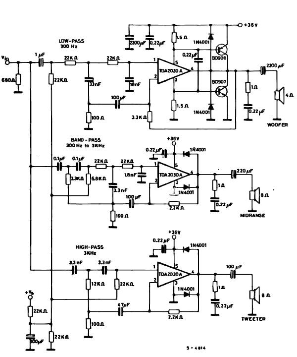
A simple multiway active speaker audio system can be designed using the TDA2030 audio IC. This TDA2030 active speaker audio system circuit is created to deliver optimal acoustic performance, as each loudspeaker is specifically designed and optimized for a...
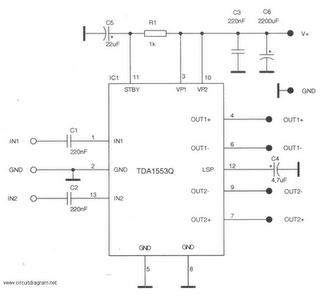
This is a 22-watt car stereo audio amplifier. The circuit is based on a single IC TDA1553 with a few peripheral components. This IC is designed for car audio applications. The TDA1553CQ integrates two 22-watt amplifiers with differential input...
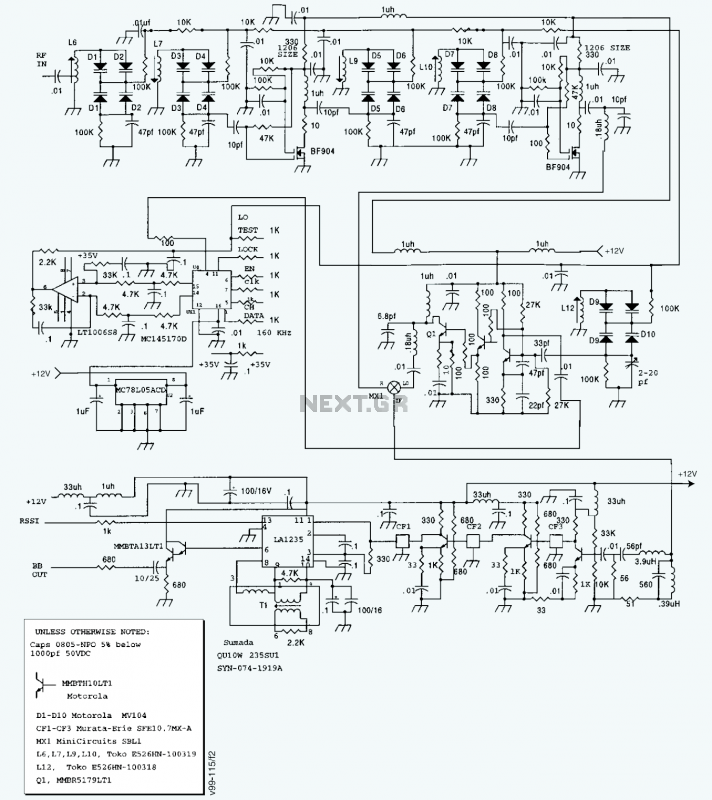
A block diagram and a schematic of the receiver are shown in Figures 2 and 3, respectively. In Figure 3, L6 and L7 are spaced 0.6 inch for a loss of about 0.5 dB. Q4 is the first RF...
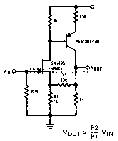
This compound series-feedback circuit provides high input impedance and stable wide-band gain for general-purpose video amplifier applications. The compound series-feedback circuit is designed to achieve high input impedance, which is essential for minimizing loading effects on the preceding stage of...