
12 Stage Neon Sequencer (NE-2 / NE-51) circuit
")
The circuit design consists of several key components that work together to achieve the desired functionality of illuminating the neon lamps in a clock-like manner. The 74HC14 Schmitt trigger serves as the oscillator, creating a square wave signal that drives the switching transistor. This transistor is responsible for controlling the flow of current to the high-Q inductor, which is crucial for stepping up the voltage to the necessary 70 volts for the neon lamps.
The use of two nickel-cadmium cells provides a reliable power source, ensuring that the circuit can function continuously for an extended period. The choice of high-capacity cells allows for a longer operational lifespan, making the circuit suitable for applications where regular battery replacement would be inconvenient.
The high-Q inductor plays a vital role in the voltage amplification process. By storing energy and releasing it at a higher voltage, it enables the neon lamps to operate effectively. The design ensures that the lamps can be lit with a consistent brightness, which is critical for visibility and aesthetic appeal.
In summary, this circuit effectively combines a low-voltage power source with a high-voltage generation mechanism to operate neon lamps, demonstrating an innovative approach to clock design using alternative lighting technology.This circuit is similar to the LED clock using 12 neon indicator lamps instead of LEDs. It operates from 2 high capacity ni-cad cells (2.5 volts) which keep it going for a couple weeks. High voltage (70 volts) for the neon lamps is obtained from a small switching power supply using a 74HC14 Schmitt trigger squarewave oscillator, high voltage switching transistor, and mH high Q inductor.. 🔗 External reference
Related Circuits
Designed for communications use, this equalizer circuit utilizes a Mitsubishi M5226P audio equalizer IC to modify frequency response. It operates with a supply voltage ranging from 9 to 20 V. Capacitors C6 through C16 are polyester film capacitors with...
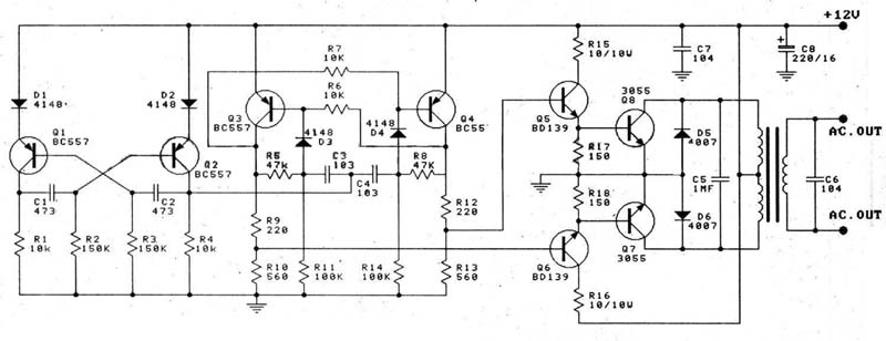
A 12V car battery is recommended as the input for this circuit, utilizing the 2N3055 transistor as the amplifier. This configuration can deliver a power output of up to 100W, making it suitable for use in battery chargers, emergency...
The power amplifier (PA) output Pi section features two variable capacitors: one ranging from 20 to 120 pF and a second, custom-built capacitor with a range of 50 to 450 pF. The latter is activated for lower frequency bands...
The FM front-end circuit, also referred to as an FM receiver circuit, is composed of discrete components. This configuration presents challenges in debugging and is prone to difficulties in miniaturization, leading to its gradual replacement by FM radio integrated...
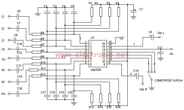
The TDA1029 is a dual operational amplifier configured as an impedance converter. Each amplifier features four mutually switchable inputs that are safeguarded by clamping diodes. Signal sources can be switched in various modes. The electronic components required for this...
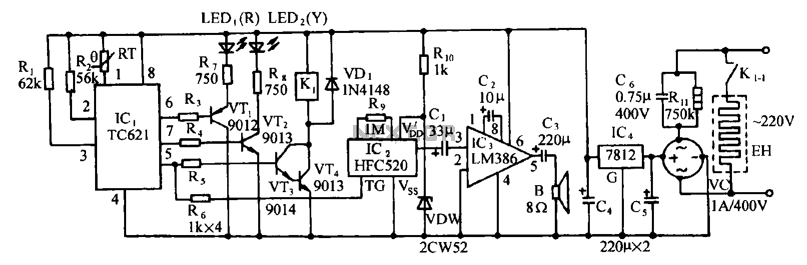
Eggs hatch chicks at temperature requirements within the range of 36 to 39 degrees Celsius. The temperature sensor integrated circuits utilize the TC621 temperature control circuit, which has fewer external components, is low cost, and offers high reliability. Users...