
120v to 3.7v circuit

The battery circuit in question likely involves several key components that are essential for proper functionality. Typically, such circuits include a battery, a charging module, and various protection elements to ensure safe operation. The salvaging process may involve reusing components such as resistors, capacitors, or integrated circuits that were previously part of a functioning system.
When integrating a salvaged circuit with a new battery, it is crucial to ensure compatibility in voltage and current ratings to prevent damage. The circuit should also include a method for monitoring the battery's state of charge, which can be accomplished through voltage dividers or dedicated battery management ICs.
Protection features, such as overcurrent protection, overvoltage protection, and thermal management, are vital to enhance the reliability and safety of the battery circuit. These can be implemented using MOSFETs, fuses, and thermistors, respectively.
Additionally, the layout of the circuit board should be carefully designed to minimize resistance and inductance, which can affect performance. Proper grounding techniques and the use of decoupling capacitors can help mitigate noise and ensure stable operation of the circuit.
In summary, salvaging a battery circuit and integrating it with a new battery requires careful consideration of component compatibility, safety features, and circuit design principles to achieve a reliable and efficient power supply solution.Oh, one thing I forgot to mention about the battery ""circuit"" I attempted to salvage the circuit and put it inline with the new battery,.. 🔗 External reference
Related Circuits
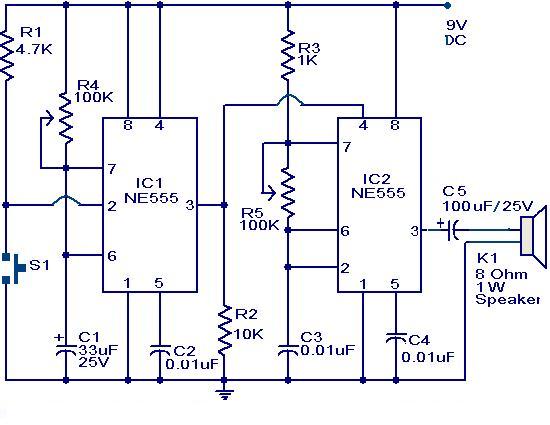
The primary component of this circuit is a doorbell utilizing two NE555 timer ICs. When the switch S1 is momentarily pressed, the speaker produces a bell sound, which is determined by the time period of the monostable multivibrator configured...

A miniature real-time controller manages night lights, air conditioning units, and household appliances with a programmable scheduler. The device utilizes modified source code and a hex file for year 2002 readout. The circuit comprises three primary chips: an 89C2051...
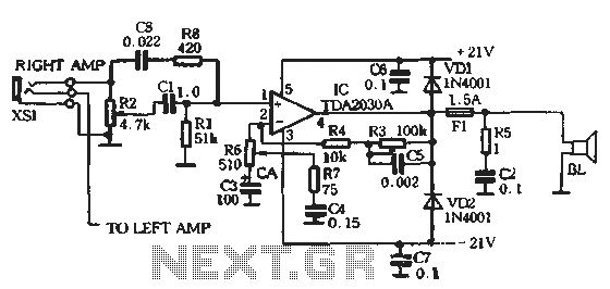
The circuit comprises two main components: the Lisheng power amplifier and the rectifier filter section. The stereo audio power amplifier circuit diagram, depicted in Figure 5-85, illustrates only one channel, with the other channel being identical. The audio signal...

The PGA202 offset voltage correction circuit is designed to correct both input and output offset voltages. There are four different gain settings for the PGA202, which result in slight variations in input offset voltage. A 50k potentiometer is used...
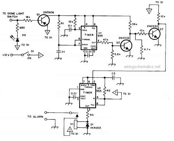
This circuit diagram represents a smart car alarm timer. This design is more advanced compared to traditional car alarm systems. When activated, the alarm remains active for 80 seconds, following an initial delay of 15 seconds. The smart car alarm...
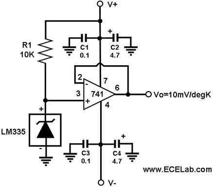
In this circuit, the LM335 is utilized as a temperature sensor, an integrated circuit that converts ambient temperature into an equivalent output voltage. The LM335 is a precision temperature sensor that provides a linear output voltage proportional to the absolute...