125_MHz_LOGIC_PROBE

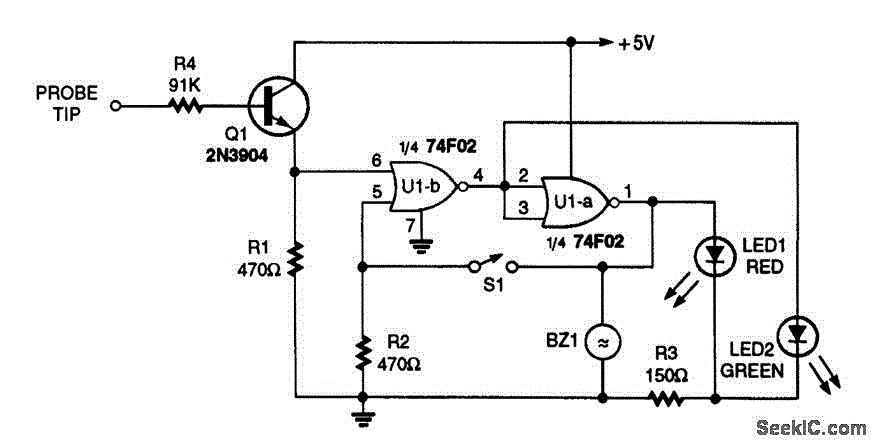
This logic probe includes high-low (LED) indication and a latching operation. When switch S1 is closed, the pulse indication is latched, causing the red LED1 to remain illuminated. A piezoelectric buzzer, BZ1, serves as an audible indicator to signal that a logic high is detected.
The logic probe circuit is designed to provide both visual and audible feedback for digital signal levels. The core components include a switch (S1), a red LED (LED1), and a piezoelectric buzzer (BZ1).
When S1 is closed, it activates a latching mechanism that holds the state of the detected pulse. This mechanism allows LED1 to remain lit, indicating that a logic high signal has been detected. The use of a red LED is typical in such applications as it provides a clear visual cue for the user.
The piezoelectric buzzer (BZ1) is employed to provide an auditory signal in conjunction with the LED indication. This feature enhances usability, especially in environments where visual observation may be challenging. The buzzer produces a sound when a logic high is present, alerting the user to the status of the signal.
In terms of circuit design, the logic probe may include additional components such as resistors to limit current through the LED and buzzer, ensuring they operate within safe parameters. A power source, typically a battery, is required to power the circuit, and appropriate connections must be made to ensure proper functionality.
Overall, this logic probe serves as an effective tool for testing and troubleshooting digital circuits, providing dual indication methods to enhance user experience and reliability in signal detection.This logic probe features either high-low (LED) indication or latching operation. When S1 closed, the indication of a pulse is latched and the red LED1 stays on. Piezoelectric buzzer BZ1 used as a beeper to sound that a logic high is preset.. 🔗 External reference