
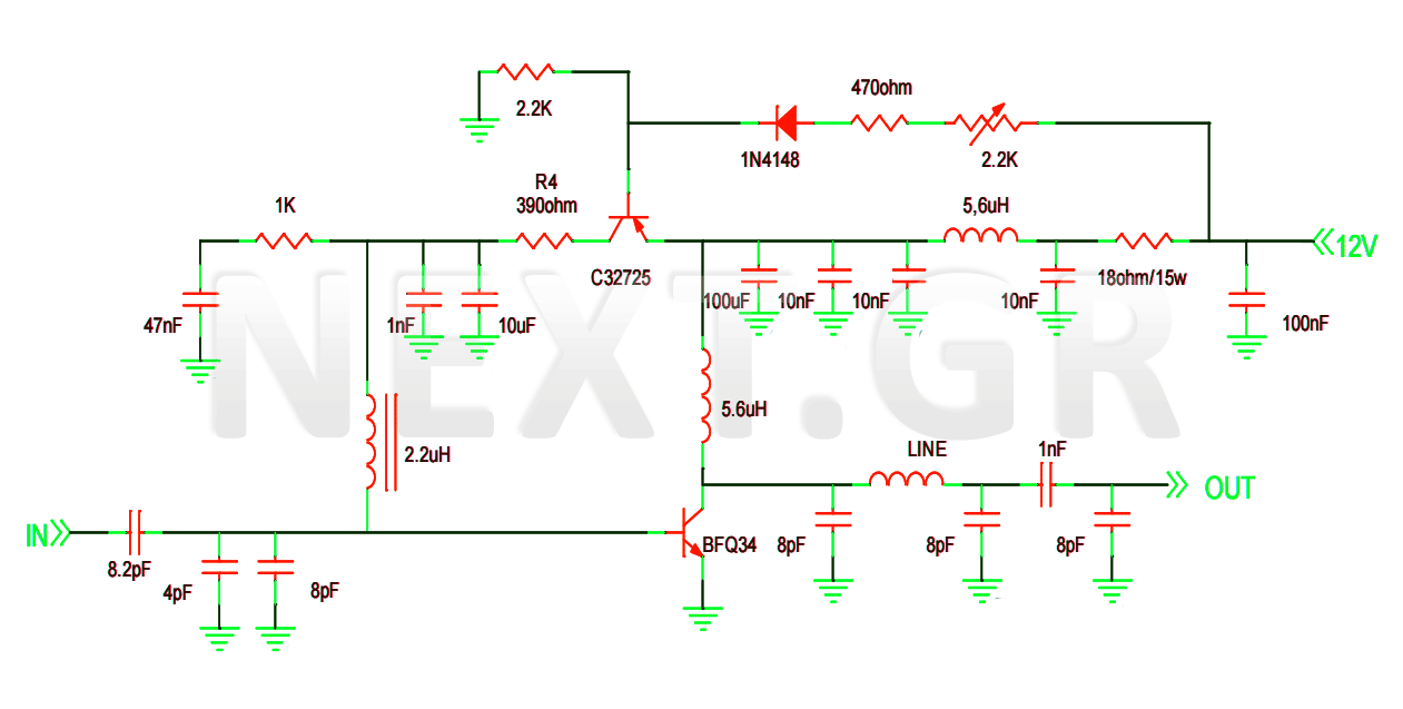
125Watt 150Mhz amplifier

The amplifier circuit is designed to function efficiently under a 28 V DC power supply, making it suitable for various applications requiring robust performance. The gain of 12 dB signifies that the amplifier can increase the power level of the input signal by a factor of approximately 4, thus enhancing the signal strength for further processing or transmission.
The ability to operate into a 30:1 Voltage Standing Wave Ratio (VSWR) indicates that the amplifier is highly resilient to mismatched loads, a critical feature in RF applications where impedance matching is often challenging. This capability ensures that the amplifier can handle reflected power without incurring damage, which is essential for maintaining operational reliability in real-world scenarios.
The output power management is particularly noteworthy. The design allows for the output power to be significantly reduced, down to less than 1 watt, while maintaining a constant input power level. This is achieved by adjusting the DC gate voltage negatively from its quiescent drain current (Idq) value. Such a feature is beneficial for applications that require dynamic power control, enabling the amplifier to adapt to varying operational conditions without compromising performance.
Furthermore, the Automatic Gain Control (AGC) feature, with a range exceeding 20 dB, allows the amplifier to automatically adjust its gain based on the input signal level. This ensures consistent output performance across a wide range of input signal strengths, enhancing the versatility of the amplifier in different operational environments. The AGC system contributes to overall system stability and prevents distortion or clipping of the output signal, making the amplifier suitable for high-fidelity applications.
In summary, this amplifier is engineered for high performance, resilience to load variations, and effective power management, making it ideal for demanding electronic applications.This amplifier operates from a 28 Vdc supply. It has a typical gain of 12 dB, and can survive operation into a 30:1 VSWR load at any phase angle with no damage. This means that with input power held constant at the level that provides 125 watts output, the output power may be reduced to less than 1.0 watt continuously by driving the dc gate voltage negative from its Idq value.
The amplifier has an AGC range in excess of 20 dB.
Related Circuits
This project involves the construction of a VHF-UHF linear amplifier capable of operating at frequencies ranging from 47 MHz to 740 MHz. It serves as the final output stage for any transmitter functioning within these frequencies. The amplifier utilizes...
This project is based almost directly on the typical application circuit in the National Semiconductor specification sheet. You can also use the TDA2050 (from SGS-Thompson), which has almost identical performance and (remarkably) the same pinouts! As it turns out,...
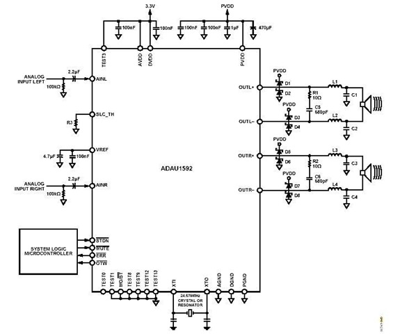
This is a stereo circuit schematic of the ADAU1592, a 2-channel, bridge-tied load (BTL) switching audio power amplifier. The ADAU1592 can be utilized in compact television sets, PC audio systems, and mini-component applications. According to the ADAU1592 datasheet, an...
Individuals seeking private listening to their music should incorporate this Headphone Amplifier into the Modular Preamplifier chain. The circuit design prioritizes simplicity while ensuring high-quality performance. This objective is achieved through the use of two NE5532 Op-Amps, where IC1B...
This is a simple low-impedance preamplifier circuit diagram used to amplify an audio signal. The circuit operates with a 12V DC power source and is straightforward due to its minimal component count. The low-impedance preamplifier circuit is designed to enhance...
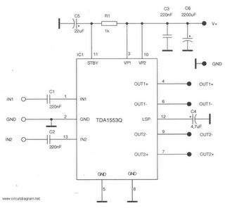
This is a 22-watt car stereo audio amplifier. The circuit is based on a single IC TDA1553 with a few peripheral components. This IC is designed for car audio applications. The TDA1553CQ integrates two 22-watt amplifiers with differential input...