
12V Battery Level Indicator Circuit

The battery level indicator circuit utilizes a series of five light-emitting diodes (LEDs) to provide a visual representation of the battery voltage level. The circuit is designed to activate each LED at specific voltage thresholds, allowing users to easily assess the battery's charge status.
The first LED, colored red, serves as a power connection indicator, illuminating when the battery is connected but not yet charged, indicating 0% charge. The second LED, colored yellow, activates when the battery voltage exceeds 10.5V, representing a charge level of approximately 25%.
As the voltage continues to rise, additional LEDs are activated at predetermined voltage levels. For instance, the third LED could illuminate at 12.0V, indicating a charge level of around 50%. The fourth LED might activate at 12.5V, representing 75% charge, while the fifth LED, typically colored green, would light up when the voltage reaches 13.0V or higher, indicating a fully charged battery.
The circuit can be implemented using a voltage divider to scale down the battery voltage to a suitable level for comparison with reference voltages. Comparators or microcontroller analog inputs can be employed to detect when the voltage crosses these thresholds, triggering the corresponding LED to light up.
This battery level indicator is particularly useful in various applications, including portable devices, electric vehicles, and renewable energy systems, where monitoring battery status is crucial for optimal performance and longevity.This battery level indicator offers (5) LEDs that light up progressively as the voltage increases: Red: Power Connected (0%) Yellow: Greater than 10.5V (25.. 🔗 External reference
Related Circuits
The laser-pointer detection circuitry is capable of identifying when a laser light is directed at a specific photosensor. If the laser targets the top sensor, the comparator chip outputs a high signal. Conversely, if the laser is aimed at...
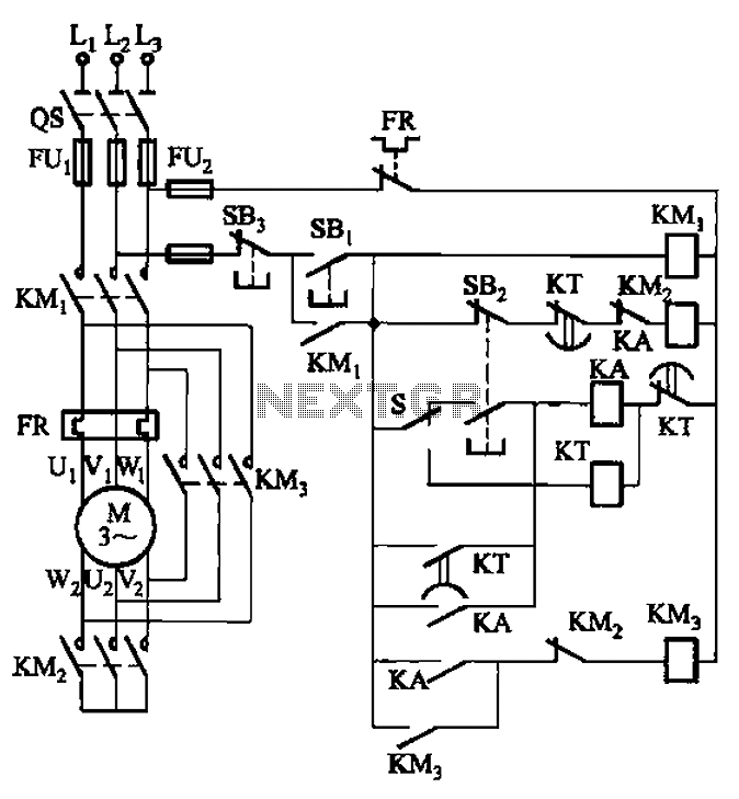
The circuit is depicted. It is capable of both manual and automatic control. The circuit in question is designed to facilitate dual modes of operation: manual and automatic control. This versatility allows users to engage with the system according to...
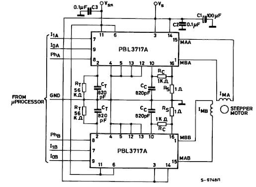
The PBL3717A stepper motor driver is a monolithic integrated circuit that controls and drives one phase of a bipolar stepper motor utilizing chopper control for phase current regulation. Current levels can be selected in three increments using two logic...

The pressure transmitter circuit data acquisition system utilizes the 1B31, an 18-bit A/D converter (AD1170), and an MCS-51 microcontroller. The configuration, as depicted in the accompanying diagram, features a full-scale output voltage of 10 mV from the pressure transmitter...
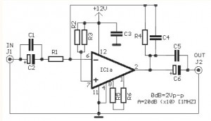
The video amplifier circuit utilizes the LM359 integrated circuit, which is a dual, high-speed, programmable current mode (Norton) amplifier. This circuit is suitable for general-purpose video amplification applications. The LM359 is designed to operate as a high-speed amplifier, making it...
This circuit features a micro vibration sensor, a trigger delay circuit, and a control circuit, as illustrated in the accompanying figure. The micro vibration sensor comprises a vibration sensing device and a high power amplifier circuit, enabling it to...