
12V Low Cost Car Battery Charger Circuit PCB

The described car battery charger circuit operates on a straightforward principle of converting AC voltage to DC, which is necessary for charging lead-acid batteries effectively. The center-tapped transformer steps down the mains voltage to a lower AC voltage, which is then rectified by diodes D1 and D2. These diodes are arranged to allow current to flow in one direction, producing a pulsating DC output.
The use of a 1-ohm wire-wound resistor serves a dual purpose. Primarily, it limits the current flowing into the battery, which is crucial for preventing damage due to overcharging. As the battery reaches its full charge, the charging current diminishes, approaching zero, which is indicated by the LED. The LED not only signifies that the circuit is active but also provides a visual cue regarding the charging status; a dim LED indicates a lower charging rate, while a brighter LED suggests that the battery is currently charging.
For those considering modifications, the circuit can be adapted for 24V batteries by adjusting the transformer turns ratio and ensuring that the diodes and resistor are rated for the increased voltage and current requirements. This flexibility makes the circuit suitable for a range of applications beyond just 12V systems.
In summary, this car battery charger circuit is an economical and efficient solution for maintaining vehicle battery health, ensuring that the battery remains charged and ready for use. Its simplicity and effectiveness make it a valuable addition to any home workshop or garage.Nowadays it has become necessary to own a car battery charger at home. By keeping one at home, we can avoid car starting trouble due to battery complaints. Buying one battery charger will cost you huge amounts while the components used in the car battery charger schematic is cheap. This charger circuit is designed for 12V car batteries, however we can tweak this circuit for a 24V charger. The charger circuit gives full wave rectified output voltage for charging lead acid batteries. The current reading become almost zero hen the battery is fully charged. the center tapped transformer, the diodes D1 and D2 constitute the unregulated supply portion. The One Ohm wire wound resistor of 10W connected in series controls the charging current and prevents the battery from overcharging. The LED shows the presence of the output voltage. Also its brightness depends on the charging rate. 🔗 External reference
Related Circuits
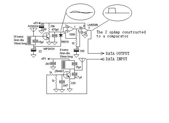
While developing an infrared (IR) extender circuit, a method was needed to measure the relative intensities of different infrared light sources. This circuit utilizes an SFH2030 photodiode as the infrared sensor. A CA3140 MOSFET operational amplifier is employed in...
According to current legislation in many countries, vintage cars must also be fitted with a rear fog lamp. Modern vehicles incorporate circuitry associated with the fog lamp switch to prevent the fog lamp from activating when the lights are...
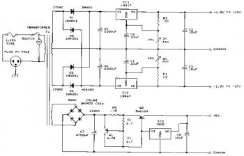
This bench power supply features three solid-state DC power supplies. The first supply provides an output of 1.5 to 15 volts at 1 ampere. The second supply offers a range of -1.5 to -15 volts at 1 ampere. The...
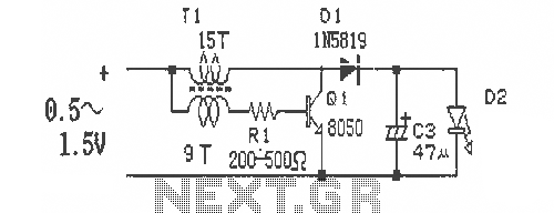
This is a simple and easy-to-build DC-DC driver circuit designed for a single flashlight battery, operating at a parametric voltage of 1.5V. The input current is 90mA, while the light-emitting diode (LED) current is 26mA or higher. The circuit...
Even including labor, the actual cost of purchasing, stocking, assembly, assembly errors, more expensive PCBs (with additional holes and larger sizes), and the increased difficulty in tuning would likely result in significantly higher expenses. The analysis of costs associated with...
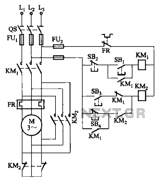
The C620 lathe Y-conversion includes a power-saving circuit designed for controlling the motor's reversing functionality. This system is applicable to machines such as the C620, C630, and CW61100A lathes, as well as radial drilling and milling machines. The C620 lathe...