
12V Relay on 6V power supply

The circuit in question is designed to enable a 12V relay to function effectively with lower voltage supplies, specifically 6V or 9V. This is particularly advantageous in applications where the available power supply is less than the nominal voltage required by the relay for its operation.
The core components include a 220µF electrolytic capacitor, a 2.2kΩ resistor, and two transistors configured as a switching mechanism. The operation begins when a control voltage exceeding 1.5V is applied to the input. This voltage triggers both transistors to enter the ON state, allowing current to flow through the circuit.
The 220µF capacitor charges through the 2.2kΩ resistor and the lower diode, which is likely a standard rectifier diode. The charging process ensures that the capacitor accumulates sufficient charge, producing a voltage across its terminals. When the transistors are activated, the voltage across the capacitor is approximately 5V. This voltage is significant as it causes the negative terminal of the electrolytic capacitor to dip below the ground reference (0V) by about 4.5V.
As a result, the relay receives an effective voltage of around 10V across its coil. This voltage is adequate for the relay to pull in and maintain its state, even though it was initially powered by a lower voltage supply. The ability of the relay to hold its position at a lower voltage (6V) is leveraged here, ensuring reliable operation without the need for a higher voltage power source.
This circuit can be utilized in various applications, including automotive systems, low-voltage control systems, and other scenarios where efficient relay operation at reduced voltages is necessary. The design emphasizes simplicity and effectiveness, making it an ideal solution for specific control tasks.This circuit allows a 12v relay to operate on a 6v or 9v supply. Most 12v relays need about 12v to "pull-in" but will "hold" on about 6v. The 220u charges via the 2k2 and bottom diode. When an input above 1.5v is applied to the input of the circuit, both transistors are turned ON and the 5v across the electrolytic causes the negative end of the electro to go below the 0v rail by about 4.5v and this puts about 10v across the relay. 🔗 External reference
Related Circuits
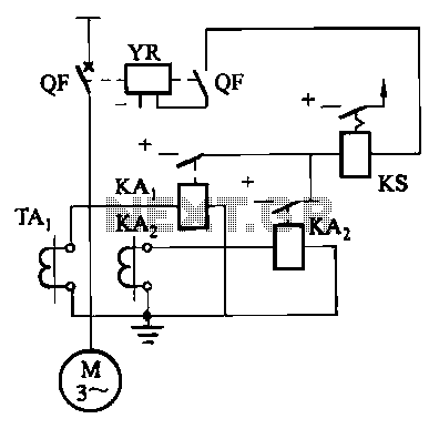
Figure 4-52 (a) illustrates the two-phase wiring for direct current (DC) operation, while Figure 4-52 (b) depicts the two-phase current differential wiring for alternating current (AC) operation. The schematic in Figure 4-52 (a) represents a two-phase wiring configuration suitable for...
A dimmer is not commonly found in a caravan or on a boat. This document outlines how to create one. If the goal is to adjust the ambiance while entertaining friends and acquaintances, this circuit allows for that capability....
Some time ago, an electronic hobbyist sought to create a logic analyzer. As a DIY enthusiast, a simple yet effective logic analyzer was constructed. Utilizing an old Pentium III laptop equipped with a single LPT port, a search for...
When constructing a dual stand-alone preamplifier, such as a stereo magnetic phono preamp, the power supply requirements are significantly reduced. A simple power supply circuit is illustrated, utilizing readily available 12-volt, 0.5-ampere transformers, although units capable of 1 ampere...
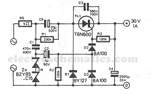
This transformerless power supply circuit is designed for medium current applications. During the negative half period, the capacitor C5 is charged to peak voltage. This transformerless power supply circuit operates by utilizing capacitive coupling to convert AC mains voltage into...
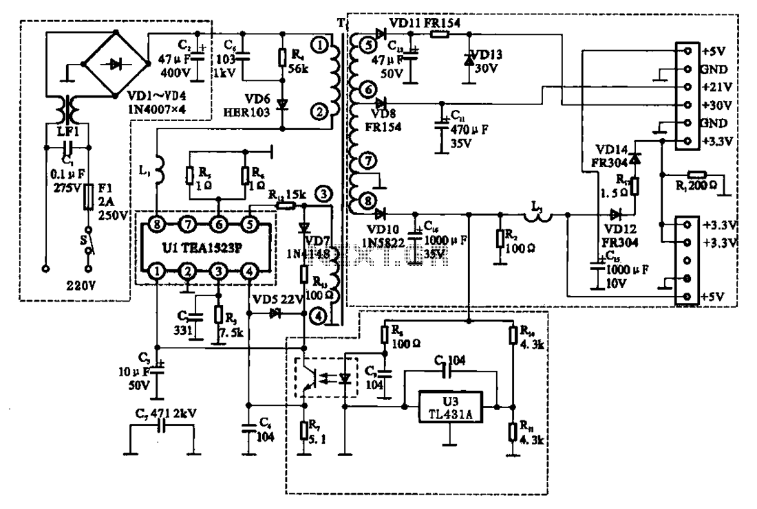
The East Shi IDS-2000F STB switching power supply circuit primarily consists of an AC input circuit, a switching oscillation circuit, an output circuit, and a secondary steady voltage control circuit. The AC input circuit includes a switch (S), fuse...