
12V smooth Flashing circuit
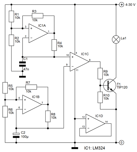
On the minus input is a capacitor to ground. This capacitor is loaded from the output of the opamp through resistor R4. The voltage across the capacitor will therefore slowly until the tension is equal to the voltage on the positive input. At that point causes the circuit to the output of the amplifier is low, and capacitor is discharged via R4. The reference voltage on the positive input will now lower, so it takes some time the capacitor is sufficiently discharged. The result is a roughly triangular voltage across the capacitor. Triangular voltage drops below the reference voltage, the output of IC1C low, the transistor Locks and the lamp goes out. Actually this is already an indicator, but the blink rate now stands at 1 kHz, so that you can not follow with your eyes (and indeed not the filament).
The height of the reference voltage to set you can adjust the width of the pulses, while pulse rate stays the same. As a result, the ratio of on-time and off time can be set, and thus the average light output of the lamp. The higher the voltage reference (Uref 1), the narrower the pulses and narrow pulses also give less light.
Signal Modulator
This circuit is the reference voltage for the pulse width modulator is from a triangle generator built around IC1b. The circuit is the same as the generator IC1a around, but the frequency is much lower because a larger capacitor is used. The result is that the reference voltage of the pulse width modulator slowly goes up (and the pulses are narrower and less light) to a maximum, and then lower (and wider and thus more light pulses).
The output transistor
The output transistor is a TIP120 signed here. That's a big darlington also a large current can switch. A car lamp 12 V 10 W transistor this would not be a problem. A darlington transistor is preferred here because the opamp IC1C can not deliver than about 5 mA. However, it may be necessary to choose a lower value for the base resistor R 9, especially when the circuit is also a low voltage to operate. This has a built darlington transistor base resistance between base and emitter so that a basic minimum distribution is required before the transistor begins to conduct. R1-R10 = 10 kOhm C1 = 47 nF C2 = 100 V ?F/35 T1 = TIP120 IC1 = LM324 For smaller bulbs or LEDs (not forget the series resistor) is a BC517 well. Its frequency can approximately be calculated using the formula T = RC, where T is the loading time (and discharge time) in seconds, R is resistance R4 (in ohms), and C is the capacity of C2 in Farad. Here is (10,000 * (47 / 1,000,000,000)) = 47 ms. The frequency of the triangular voltage is about 1 kHz. Opamp IC1C provides the pulse-width modulation. On the plus input, the delta IC1a tension and the minus input is a reference voltage. If the triangle voltage exceeds the reference voltage, the output of the opamp high, the transistor will receive base current and the lamp turns on. The amplitude of the triangle voltage can be adjusted by changing R3. A lower resistance produces a higher voltage triangle, but the flanks are slightly less right. And it also affects the frequency.
The circuit operates by utilizing an operational amplifier (op-amp) configured as a triangular waveform generator. The op-amp (IC1a) generates a triangular voltage that oscillates between two reference levels determined by the resistor divider (R1 and R2). Resistor R3 modifies the charge and discharge paths, allowing the circuit to toggle between approximately one-third and two-thirds of the supply voltage.
The capacitor connected to the negative input of the op-amp charges through resistor R4. As the capacitor charges, its voltage approaches the positive input voltage, causing the output of the op-amp to switch states. When the output goes low, the capacitor discharges through R4, and the cycle repeats, creating a triangular waveform.
The output of the op-amp (IC1C) is used for pulse width modulation (PWM) control of a transistor (T1, TIP120), which drives the lamp. The PWM frequency is determined by the charge and discharge times of the capacitor, which can be calculated using the formula T = RC. This results in a blinking effect where the lamp gradually brightens and dims based on the triangular waveform's amplitude and frequency.
The circuit allows for adjustment of the average light output by varying the reference voltage (Uref 1), which alters the pulse width while maintaining the same frequency. As the reference voltage increases, the pulse width decreases, resulting in less light output.
In summary, the described circuit provides a versatile solution for controlling the brightness of a lamp using PWM, with adjustable parameters to fine-tune the output characteristics. The use of a Darlington transistor allows for efficient switching of higher loads, making this circuit suitable for various applications requiring gradual illumination changes.This circuit ensures that a blinking slowly, ie the lamp is brighter lights until a maximum is reached and then gradually decrease in strength until the lamp is off. IC1a opamp is used here to a triangular voltage generation. The opamp acts as a comparator, ie the output is at full power. If the positive input is higher than the minus input, the output of the opamp high and low otherwise.
The resistor divider R1/R2 ensures that half the supply voltage to the positive input of the opamp state, but R3 is in parallel with R1 when the output is high, and parallel to R2 if the output is low. This input toggles between still 1 / 3 and 2 / 3 of the supply voltage. On the minus input is a capacitor to ground. This capacitor is loaded from the output of the opamp through resistor R4. The voltage across the capacitor will therefore slowly until the tension is equal to the voltage on the positive input. At that point causes the circuit to the output of the amplifier is low, and capacitor is discharged via R4.
The reference voltage on the positive input will now lower, so it takes some time the capacitor is sufficiently discharged. The result is a roughly triangular voltage across the capacitor. Triangular voltage drops below the reference voltage, the output of IC1C low, the transistor Locks and the lamp goes out.
Actually this is already an indicator, but the blink rate now stands at 1 kHz, so that you can not follow with your eyes (and indeed not the filament). The height of the reference voltage to set you can adjust the width of the pulses, while pulse rate stays the same.
As a result, the ratio of on-time and off time can be set, and thus the average light output of the lamp. The higher the voltage reference (Uref 1), the narrower the pulses and narrow pulses also give less light.
Signal Modulator This circuit is the reference voltage for the pulse width modulator is from a triangle generator built around IC1b. The circuit is the same as the generator IC1a around, but the frequency is much lower because a larger capacitor is used.
The result is that the reference voltage of the pulse width modulator slowly goes up (and the pulses are narrower and less light) to a maximum, and then lower (and wider and thus more light pulses). The output transistor The output transistor is a TIP120 signed here. That's a big darlington also a large current can switch. A car lamp 12 V 10 W transistor this would not be a problem. A darlington transistor is preferred here because the opamp IC1C can not deliver than about 5 mA. However, it may be necessary to choose a lower value for the base resistor R 9, especially when the circuit is also a low voltage to operate.
This has a built darlington transistor base resistance between base and emitter so that a basic minimum distribution is required before the transistor begins to conduct. R1-R10 = 10 kOhm C1 = 47 nF C2 = 100 V ?F/35 T1 = TIP120 IC1 = LM324 For smaller bulbs or LEDs (not forget the series resistor) is a BC517 well.
Its frequency can approximately be calculated using the formula T = RC, where T is the loading time (and discharge time) in seconds, R is resistance R4 (in ohms), and C is the capacity of C2 in Farad. Here is (10,000 * (47 / 1,000,000,000)) = 47 ms. The frequency of the triangular voltage is about 1 kHz. Opamp IC1C provides the pulse-width modulation. On the plus input, the delta IC1a tension and the minus input is a reference voltage. If the triangle voltage exceeds the reference voltage, the output of the opamp high, the transistor will receive base current and the lamp turns on.
The amplitude of the triangle voltage can be adjusted by changing R3. A lower resistance produces a higher voltage triangle, but the flanks are slightly less right. And it also affects the frequency. 🔗 External reference
Related Circuits
The BA3884 operates with a DC voltage range of 5.4 to 12.3V. Its internal circuit design and application circuit are represented in Figure 5-16. This circuit consists of a dual-channel processing system, which processes audio signals through two identical...

Several individuals have struggled to locate the transformer necessary for the Black Light project. Consequently, an investigation was conducted to identify a fluorescent lamp driver that does not necessitate any specialized components. A suitable option was discovered in Electronics...
Voltage regulator ICs from the 78xx series deliver a stable output voltage in contrast to a highly variable input supply, provided that the common terminal is grounded. Any voltage applied above zero volts (ground) to the common terminal is...
This is the discharging circuit. The red lines indicate the flow of energy from the capacitors to the terminals when the switch is in the upward position. The circuit is complete due to the connection of the terminals by...
The use of a quarter-wave parallel-wire line as a tuning unit has been discussed in the chapter on Short Lines, where it was pointed out that these circuits have comparatively high Q even at higher frequencies. Their great length...
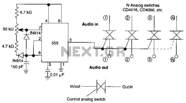
A 555 timer can be configured to simulate a multi-gang potentiometer by controlling the mark-space ratio. The switching rate should be at least twice the maximum expected signal frequency that the potentiometer has to handle. The 555 timer is an...
Warning: include(partials/cookie-banner.php): Failed to open stream: Permission denied in /var/www/html/nextgr/view-circuit.php on line 713
Warning: include(): Failed opening 'partials/cookie-banner.php' for inclusion (include_path='.:/usr/share/php') in /var/www/html/nextgr/view-circuit.php on line 713